Telex Airman 750 Maintenance & Overhaul Manual
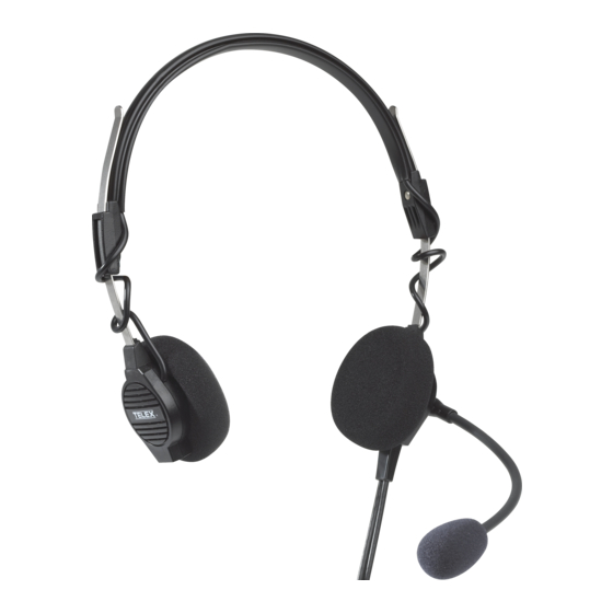
Headset and headphone
Hide thumbs
Also See for Airman 750:
- Brochure & specs (20 pages) ,
- Customer maintenance manual (32 pages)

Related Manuals for Telex Airman 750


Summary of Contents for Telex Airman 750
- Page 1 Airman 750 / 760 Headset and Headphone Maintenance & Overhaul Manual for Airman 750/760 Headset & Headphone F.01U.311.532 Rev. 09 Component Maintenance Manual August/2018...
- Page 2 Airman 750/760 Record of Revisions Rev No. Revision Date Change Description 12/1988 06/1989 01/1990 11/1993 See previous revisions of 38108-965 for affected changes 03/1995 04/1996 06/2000 07/2017 This document was completely rewritten and a Bosch part number (F.01U.311.532) was assigned.
- Page 3 Airman 750/760 Purpose of Manual This manual, Bosch part number F.01U.311.532, contains information for the overhaul and servicing of the Airman 750/760 headsets. Technical Support A liaison between the customer and factory is provided by the Bosch Product Support Department. Consultation and assistance on technical problems, part information, and availability of local and factory repair facilities is available.
- Page 4 Airman 750/760...
-
Page 5: Table Of Contents
2.1 Parts List..........................11 2.1.1 General .......................... 11 2.1.2 Airman 760, Catalog Number 64400-200..............12 2.1.3 Airman 750, Catalog Number 64300-200, -205, -208, -210, -212, -218, -219, -220, -300 2.2 Disassembly/Assembly ......................15 2.2.1 Disassembly ........................15 2.2.1.1 Removal of the Receiver Assembly ..............15 2.2.1.2 Removal of the Cord Assembly ................ - Page 6 4.1 Microphone Validation and Adjustment................. 27 4.1.1 Microphone/Amplifier Sensitivity Check..............27 4.1.2 Microphone Sensitivity Adjustment ................28 4.2 Circuit Board - 200/300 Series Airman 750 ................29 4.2.1 Testing the Circuit Board Assembly................30 4.3 Speaker Validation........................30 4.3.1 Speaker Sensitivity and Frequency Response Verification ........... 30 4.4 Mechanical Maintenance ......................
-
Page 7: Description & Specifications
1.1 Description/Specifications 1.1.1 General Description The Telex Airman 750 Headset and the Airman 760 Headphone are designed and engineered for high-quality aircraft communications. The Airman 750 is approved for aircraft use under the Federal Aviation Agency TSO C57a and C58a. The Airman 760 is approved for aircraft use under the Federal Aviation Agency TSO C57a. -
Page 8: Models Covered
8 Description & Specifications Airman 750/760 CMM 1.1.2 Models Covered Airman 750/760 Models and Connector TABLE 1. Model Number Description Connector Airman 750 64300-200 Double side headset, 2x PJ, 150 PJ-068/PJ-055 (or equivalent) 64300-205 Double side headset, 2x A5M, 150... - Page 9 Airman 750/760 CMM Description & Specifications 9 Sensitivity: ref. 1V/bar @1kHz, 12VDC -51 +3/-3dB (All versions except -220) -44 +2/-1dB (-220) Operating Voltage: 8-16 Vdc (470 Ohm load) Approximate Gross Weight: Single-Sided 4oz. (113g) Double-Sided 4.8oz. (136g) 3oz. (85g) Approximate Wearing Weight: Single-Sided 2.3oz.
- Page 10 10 Description & Specifications Airman 750/760 CMM...
-
Page 11: Parts List And Disassembly/Assembly
Figure 2.1.3, “Airman 750, Catalog Number 64300-200, -205, -208, -210, -212, -218, -219, -220, -300,” on page 12 or “Airman 750, Catalog Number 64300-200, -205, -208, -210, -212, -218, -219, -220, -300” on page 12. -
Page 12: Airman 760, Catalog Number 64400-200
S-F01U327240 GLIDER SPRING(10-pack) Not Available as a replaceable part CIRCUIT BOARD F01U327242 HOUSING REAR, LEFT SIDE 2.1.3 Airman 750, Catalog Number 64300-200, -205, -208, -210, -212, -218, -219, -220, -300 MODEL Item Ordering Part Description Number SCREW, PT, PAN HEAD, K15... - Page 13 Airman 750/760 CMM Parts List and Disassembly/Assembly 13 MODEL Item Ordering Part Description Number CORD Approximate Length: 70413002 5.5 ft (1.67 m) 63988018 CORD Approximate Length: 5.8 ft (1.76m) CORD Approximate Length: 63988025 7 ft. (2.13 m) CORD Approximate Length: ...
- Page 14 14 Parts List and Disassembly/Assembly Airman 750/760 CMM MODEL Item Ordering Part Description Number 64310000 GLIDER ASSEMBLY 64305000 GLIDER SPRING 1-piece S-F01U327240 GLIDER SPRING 10-piece 600578000 PCBA 64307008 BOOM ASSEMBLY 64307013 BOOM ASSEMBLY 59688000 WINDSCREEN 800456001 WINDSCREEN + O-RING 580001003...
-
Page 15: Disassembly/Assembly
Airman 750/760 CMM Parts List and Disassembly/Assembly 15 2.2 Disassembly/Assembly The following procedure allows for complete disassembly of the Airman 750 and Airman 760. See Figure 1, Figure 2, and the “Parts List” on page 13 for reference. NOTE: Assembly is the reversal of the disassembly procedure. -
Page 16: Removal Of The Circuit Board And Boom Assembly (Airman 750)
To remove the circuit board, do the following: 1. Follow steps 1-2 in the procedure for removing the cord assembly (2.1.2). 2. If disassembling an Airman 750, use a soldering iron on the circuit board to carefully disconnect the two boom wires from J10 and J11. ... -
Page 17: Removal Of A Glider
Airman 750/760 CMM Parts List and Disassembly/Assembly 17 2.2.1.4 Removal of a Glider To remove a glider from the headset, do the following: 1. Using a pair of needle nose pliers, straighten the crimp at the end of the glider. - Page 18 18 Parts List and Disassembly/Assembly Airman 750/760 CMM...
-
Page 19: Chapter 3 Wiring / Connectors
3.1.1 Airman 750 Wiring Diagrams On the speaker, the positive terminal is usually indicate with a dot. NOTE: 3.1.1.1 Catalog Numbers 64300 -200, -220, -300 *with model -300, omit overhead cordage Airman 750 Headset Model -200, -220, -300 Wiring Diagram FIGURE 1. -
Page 20: Catalog Number 64300 -210
20 Wiring / Connectors Airman 750/760 CMM 3.1.1.2 Catalog Number 64300 -210 Airman 750 Headset Model -210 Wiring Diagram FIGURE 2. 3.1.1.3 Catalog Numbers 64300 -205, -208 Airman 750 Headset Models -205, -208 Wiring Diagram FIGURE 3. -
Page 21: Catalog Number 64300 -212
Airman 750/760 CMM Wiring / Connectors 21 3.1.1.4 Catalog Number 64300 -212 Airman 750 Headset Model -212 Wiring Diagram FIGURE 4. 3.1.1.5 Catalog Number 64300 -218 Airman 750 Headset Model -218 Wiring Diagram FIGURE 5. -
Page 22: Catalog Number 64300 -219
22 Wiring / Connectors Airman 750/760 CMM 3.1.1.6 Catalog Number 64300 -219 Airman 750 Headset Model 219 -Wiring Diagram FIGURE 6. 3.1.2 Airman 760 Wiring Diagrams 3.1.2.1 Catalog Number 64400-200 Airman 760 Headphone Model -200 Wiring Diagram FIGURE 7. -
Page 23: Airman 750 Connectors
Airman 750/760 CMM Wiring / Connectors 23 3.1.3 Airman 750 Connectors 3.1.3.1 Connector View for Catalog Numbers 64300-200, -212, -300 Microphone: .206 in. (5.2mm) DIA. Receiver: .250 in. (6.4mm) DIA PJ068 and PJ055 Connector, 750 Model -200, -212, -300 FIGURE 8. -
Page 24: Connector View For Catalog Number 64300-218
24 Wiring / Connectors Airman 750/760 CMM 3.1.3.3 Connector View for Catalog Number 64300-218 PJ-068: .206 in. (5.2mm) DIA. PJ-068 Connector, 750 Model -218 FIGURE 12. PJ-068 Connector Wiring, 750 Model -218 FIGURE 13. 3.1.3.4 Connector View for Catalog Number 64300-219... -
Page 25: Connector View For Catalog Number 64300-220
Airman 750/760 CMM Wiring / Connectors 25 3.1.3.5 Connector View for Catalog Number 64300-220 Microphone: .206 in. (5.2mm) DIA. Right Angle Receiver: .250 in. (6.4mm) DIA. Right Angle PJ068 and PJ055 Connector, 750 Model -220 FIGURE 16. PJ055 and PJ068 Connector Wiring, 750 Model -220 FIGURE 17. - Page 26 26 Wiring / Connectors Airman 750/760 CMM...
-
Page 27: Chapter 4 Maintenance
1. Construct a test circuit. For more information, see Figure 1. 2. Connect the test circuit to the microphone plug of the headset. For more information, “Airman 750/760 Models and Connector” on page 8. Airman 750 Headset Boom Microphone Sensitivity Check Test Circuit FIGURE 1. 3. Calibrate a lab microphone. -
Page 28: Microphone Sensitivity Adjustment
28 Maintenance Airman 750/760 CMM 9. Measure the output of the headset microphone with a digital volt meter. Microphone Sensitivity Specifications TABLE 1. Artificial All versions Microphone Sensitivity Mouth except -220: Specification Output @100dB – 63mVrms +16/-7mVrms @114dB – 316mVrms +82/-34mVrms For -220 use: @100dB –... -
Page 29: Circuit Board - 200/300 Series Airman 750
4.2 Circuit Board - 200/300 Series Airman 750 The same circuit board is used in all 200 and 300 Series versions of the Airman 750 Headset Circuit boards may be tested while outside of the headset chassis using the test circuit shown in Figure 4. -
Page 30: Testing The Circuit Board Assembly
Frequency Must meet standards outlined in the specifications. Response: Earphone testing for the Airman 750 and 760 is done on a flat plate coupler. For more information, see Figure 5. To measure the speaker, do the following: 1. Calibrate a lab microphone. -
Page 31: Mechanical Maintenance
Airman 750/760 CMM Maintenance 31 6. Adjust the voltage across the headset per Table 2. VOLTAGE ACROSS SPEAKER VERSION IMPEDANCE HEADSET PLUG WIRING 64300-200, -205, -208, 150 .39 VRMS Parallel -218, -219, -220 64400-200 300 .39 VRMS Stereo 64300-300 600 ... - Page 32 32 Maintenance Airman 750/760 CMM...
-
Page 33: Troubleshooting
CHAPTER 5 Troubleshooting 5.1 Troubleshooting Chart Receiver Inoperative Microphone Inoperative Receiver Intermittent Microphone Intermittent Distorted Receiver Signal Distorted Microphone Signal Microphone Level Cannot be Adjusted Properly... - Page 34 Bosch Security Systems, Inc. 12000 Portland Avenue South Burnsville, MN 55337 U.S.A. www.boschcommunications.com...
Need help?
Do you have a question about the Airman 750 and is the answer not in the manual?
Questions and answers