Advertisement
Quick Links
SKU: #xxxxx
Model: #SW23050
USE AND CARE GUIDE
xxxx
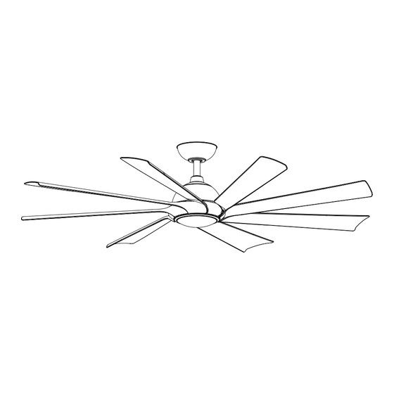
LED 60 INCH CEILING FAN
THANK YOU
We appreciate the trust and con dence you have placed in Hampton Bay through the purchase of this celing fan.
We strive to continualcreate guality products designed to enhance your home. Visit us online to see our
full line of products available for your homeimprovement needs. Thank you for choosing Hampton Bay!
Advertisement

Subscribe to Our Youtube Channel
Related Manuals for HAMPTON BAY SW23050


Summary of Contents for HAMPTON BAY SW23050
- Page 1 LED 60 INCH CEILING FAN THANK YOU We appreciate the trust and con dence you have placed in Hampton Bay through the purchase of this celing fan. We strive to continualcreate guality products designed to enhance your home. Visit us online to see our...
- Page 2 Table of Contents...
- Page 3 xxxxxxx Summer Wind International Ltd.
- Page 4 or, at our option, gives 60 in. (xxx (xxx (xxx...
- Page 5 16+1 spare 16+1 spare Metal washer 1 set 3+1 spare Remote wall cradle hardware pack (ST3.5*13mm screw -2pcs, 1 set ST3.0*18mm screw-2pcs, #6/32*13mm screw-2pcs, anchor -2pcs)
- Page 6 SUMMER WINTER FAN DIRECTION HOLD 3 SEC. 1.5V Flywheel (preassembled) Metal shade Remote control Remote wall cradle 1.5V Coupling...
- Page 7 UL Listed fuse electrical...
- Page 8 fan motor assembly coupling set screws (II).
- Page 9 Hanging the fan motor assembly to the mounting bracket Slip the coupling cover (G), canopy cover (D), and canopy (C) onto the downrod (F). Carefully reinstall the hanger ball (E) onto the downrod (F), and ensure that the cross pin (EE) is in the correct position, the set screws (HH) are tight, (MM) and the wires are not twisted.
-
Page 10: Installing The Receiver
Installing the receiver Insert the receiver (L) into the mounting bracket (B) with the ventilated side facing down. Wires coming from the downrod and the wires coming from the power source need to be positioned on the same side when inserting the receiver through the mounting bracket. - Page 11 Remember to shut the power off at the circuit breaker or fuse box. Follow the steps below to connect the fan to your house supply wires. Secure the wire nuts by wrapping the connection with electrical tape. White Black Motor to Receiver Electrical Connections: Connect the male connector from the motor to the female connector from the receiver (L).
- Page 12 Removed one screw (JJ) from the mounting bracket (B), and loosen the other screw (JJ) around 1/4" .
- Page 13 Fastening the blades to the fan motor assembly Align the 2 holes from the blade(A) to the ywheel (I). Secure the blade with two blade washer (AA) and two metal washer (BB) provided. Follow the same process for the remaining seven blades (A).
- Page 14 To reduce the risk of electric shock, CAUTION: disconnect the electrical supply circuit to the fan before installing the light kit. the switch box (00)
- Page 15 Installing the metal shade If you want the fan to be without light, please skip the last step #9 and install the metal cap directly. Raise the metal cap (K) up against the switch box (00) of the fan motor assembly (H) and secure it to fan by turning it clockwise snug.
- Page 16 Mounting the remote wall cradle The remote wall cradle is designed to allow you to NOTE: access an existing switch. The remote wall cradle can be mounted on the wall or to the face plate of a standard Toggle switch face plate toggle switch or a paddle switch.
- Page 17 SYNCING THE RECEIVER AND THE REMOTE CONTROL Install two 1.5V batteries (O) into the remote control. To prevent damage to the remote control, remove the batteries if not used for long periods of time. Restore power to the ceiling fan and test for proper operation. Do not short-circuit, disassemble, heat up, WARNING: connect improperly, or dispose of used batteries in fire.
- Page 18 REMOTE CONTROL OPERATING INSTRUCTIONS : Press and release this button to turn the fan and light on/off. Fan & Light ALL ON/OFF The fan has memory function. It will resume NOTE: the speed and light setting on the ceiling fan prior to the power being turned off.
-
Page 19: Reverse Function
REVERSE FUNCTION Reverse function button: Controls the fan direction. SUMMER WINTER To change the direction of the rotation of the NOTE: blades the fan must be in operation. Summer SUMMER Winter WINTER... - Page 22 SUMMER WINTER FAN DIRECTION HOLD 3 SEC. 1.5V Coupling Flywheel Remote wall cradle hardware pack (ST3.5*13mm Metal shade screw -2pcs, ST3.0*18mm screw-2pcs, #6/32*13mm screw-2pcs, anchor -2pcs) Remote control Remote wall cradle 1.5V...
- Page 23 HAMPTON BAY xxxxx...
Need help?
Do you have a question about the SW23050 and is the answer not in the manual?
Questions and answers