
Related Manuals for HAMPTON BAY Savona Tiffany


Summary of Contents for HAMPTON BAY Savona Tiffany
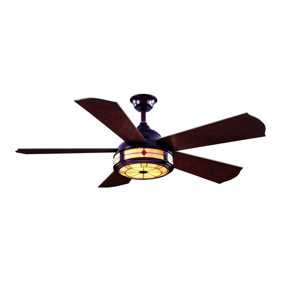
- Page 1 285 987 Savona Tiffany Ceiling Fan Owner’s Manual Savona Tiffany Ventilador de Techo de 1,32 Manual del Propietario...
-
Page 2: Table Of Contents
52” Savona Tiffany Thank you for purchasing our ceiling fan. This product has been manufactured with the highest standards of safety and quality. Ceiling Fan by Hampton Bay Date Purchased Table of Contents Store Purchased Safety Rules ....1 285-987 UL Model No. -
Page 3: Safety Rules
Safety Rules - Read and Save These Instructions To reduce the risk of electric shock, insure electricity has been turned off After making electrical connections, spliced conductors should be turned at the circuit breaker or fuse box before beginning. upward and pushed carefully up into outlet box. The wires should be spread apart with the grounded conductor and the equipment-grounding All wiring must be in accordance with the National Electrical Code conductor on one side of the outlet box and ungrounded conductor on the... -
Page 4: Unpacking Your Fan
Unpacking Your Fan Unpack your fan and check the contents. You should have the following items: LIGHT / DIMMER FAN OFF REVERSE Set of blades (5) Light plate Blade Attachment Hardware (16 Screws with Lock Washers) Canopy assembly Glass shade Ball/downrod assembly (1) Receiver+6 wire nuts Electrical Hardware... -
Page 5: Installing Your Fan
Installing Your Fan Provide Strong Support Tools Required Figures 1~3 are examples of different ways to mount the outlet box. Phillips screwdriver, straight slot screwdriver, step ladder and wire cutters. Recessed Ceiling Outlet Box Mounting Plate Mounting Options Figure 3 Outlet Box Note: You may need a longer downrod to If there isn't an existing UL listed mounting box,... - Page 6 Hanging the Fan WARNING Motor Wires FAILURE TO PROPERLY INSTALL COTTER PIN REMEMBER to turn off the power. Follow the AS NOTED IN STEP 5 COULD RESULT IN FAN Pin in Locked LOOSENING AND POSSIBLY FALLING. Ceiling Canopy Positioon steps below to hang your fan properly. Remove the decorative canopy bottom cover Tighten two set screws at top of the fan motor Ball/Downrod...
-
Page 7: Changing The Downrod
Changing the Downrod Installing Fan to UL Listed Outlet Box the Electrical Box (Optional) NOTE: Your fan comes with a 4" downrod WARNING 120V attached to the hanger ball. In addition you have Wires TO REDUCE THE RISK OF FIRE, ELECTRIC been provided with a 6"... -
Page 8: Making The Electrical Connections
Making the Electrical receiver. Secure the wire connections with the plastic wire connecting nuts provided. Connections Frequency Switch (Figure 11) Receiver to house supply wires electrical connections: Connect the black (hot) WARNING wire from the ceiling to the black wire marked TO AVOID POSSIBLE ELECTRICAL SHOCK, BE "AC in L"... - Page 9 WARNING SUPPLY CIRCUIT CHECK TO SEE THAT ALL CONNECTIONS ARE Outlet Box TIGHT, INCLUDING GROUND, AND THAT NO BARE WIRE IS VISIBLE AT THE WIRE NUTS. Ground EXCEPT FOR THE GROUND WIRE. Ceiling Conductor BLACK Mounting Bracket WARNING Outlet Box Screws ELECTRICAL DIAGRAMS...
-
Page 10: Attaching The Fan Blades
Attaching the Fan Blades Blade Balancing The following procedure should correct most fan Insert the blade through the blade slot in the Touching Ceiling decorative housing. Align the holes in blade wobble. Check after each step. and blade arm, place the blade arm plate on Check that all blade and blade bracket screws blade as showing in Figure 13, making sure the are secure. -
Page 11: Installing The Light Kit
Installing the Light Kit CAUTION Remove the screw and washer from the light plate, raise the glass shade up against the light BEFORE STARTING INSTALLATION, DISCON- plate, place looped end of safety cable over the NECT THE POWER BY TURNING OFF THE CIRCUIT BREAKER OR REMOVING THE FUSE screw and washer just removed and then secure AT FUSE BOX. -
Page 12: Operating Your Transmitter
Operating Your Transmitter Installing the Battery: Restore power to the ceiling fan and test for LIGHT / DIMMER proper operation. Install 9 volt battery (not included), to prevent "HI, MED, LO" buttons: damage to transmitter, remove the battery if not These three buttons are used to set the fan FAN OFF used for long periods (Figure 17). - Page 13 NOTE TO OPERATE THE REVERSE FUNCTION ON THIS FAN, PRESS THE REVERSE BUTTON WHILE THE FAN IS RUNNING. Speed settings for warm or cool weather depend on factors such as the room size, ceiling height, number of fans, etc. Warm weather - (Counter-Clockwise direction) A downward air flow creates a cooling effect.(Fig.
-
Page 14: Care Of Your Fan
Care of Your Fan Troubleshooting PROBLEM SOLUTION Here are some suggestions to help you maintain your fan. Fan will not start Check main and branch circuit fuses or breakers. Because of the fan's natural movement, some Check line wire connections to the fan and switch wire connections in connections may become loose. -
Page 15: Specifications
Specifications FAN SIZE SPEED VOLTS AMPS WATTS N.W. G.W. C.F. 0.32 1200 11.29 kgs 12.59 kgs 52” MED. 0.52 3850 2.6’ (28.84 lbs) (27.70 lbs) 0.59 6500 HIGH These are approximate measures. They do not include Amps and Wattage used by the light kit. -
Page 16: Warranty Information
Lifetime Limited Warranty (lifetime warranty on motor) The Hampton Bay warrants the fan motor to be free from defects in workmanship and material present at time You must present a copy of the original purchase receipt to obtain warranty of shipment from the factory for a period of lifetime after the date of purchase by the original purchaser.
Need help?
Do you have a question about the Savona Tiffany and is the answer not in the manual?
Questions and answers