Table of Contents
Advertisement
Quick Links
Advertisement
Table of Contents

Related Manuals for HAMPTON BAY 597-730


Summary of Contents for HAMPTON BAY 597-730
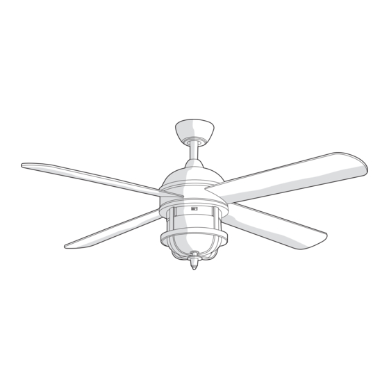
- Page 1 Item #597-730 Model #24816-021 USE AND CARE GUIDE SENZE 52 INCH CEILING FAN ASSEMBLY Questions, problems, missing parts? Before returning to the store, call Hampton Bay Customer Service 8 a.m. - 6 p.m., EST, Monday-Friday 1-877-527-0313 HAMPTONBAY.COM THANK YOU...
-
Page 2: Assembling The Fan
Assembly - Assembling the Fan Body Preparing the canopy Preparing the motor □ □ Remove the canopy bottom cover (C) from the canopy Remove the clevis pin (GG) and cotter pin (HH), and (B) by turning the canopy bottom cover (C) counter- loosen the two collar setscrews (II) from the fan clockwise. - Page 3 Assembly — Hanging the Fan Hanging the fan from the Attaching the mounting bracket mounting bracket to the electrical box WARNING: To reduce the risk of fire, electric shock, or WARNING: The tab in the ring must rest in the groove of other personal injury, mount the fan only to an outlet box or the hanger ball/downrod assembly (D).
- Page 4 Assembly — Preparing the Remote Control Preparing the receiver and remote control WARNING: To avoid possible electrical shock, ensure electricity is turned off at the main fuse box before connecting the wiring. CAUTION: The frequency switches on the receiving unit are covered with a rubber cover.
-
Page 5: Making The Electrical Connections
Assembly — Making Electrical Connections Making the electrical connections □ If your outlet box (NN) has a ground wire (HHH) (green WARNING: Check to see that all connections are tight, or bare copper) connect it to the fan ground wire (III); including the ground, and that no bare wire is visible at the otherwise connect the hanger ball/downrod assembly wire nuts, except for the ground wire. -
Page 6: Installing The Canopy
Assembly — Completing the Fan Body Attaching the canopy Installing the canopy bottom cover □ Attach the canopy bottom cover (C) to the mounting WARNING: Make sure the tab on the mounting bracket (A) bracket screw (BB) heads on the bottom of the properly sits in the groove in the hanger ball/downrod canopy (B) by inserting the screw heads into the key assembly (D) before attaching the canopy (B) to the mounting... -
Page 7: Attaching The Fan Blades
Assembly — Attaching the Fan Blades Attaching the Fan Blades WARNING: To reduce the risk of personal injury, do not bend the blades (G) while installing, balancing the blades (G), or cleaning the fan. WARNING: Do not insert foreign objects between rotating fan blades (G). - Page 8 Assembly — Installing the Light Kit Attaching the light kit mounting Attaching the light kit to plate to the mounting ring the mounting plate □ □ Remove one of the three mounting plate screws (JJ) Remove one of the three light kit mounting screws from the mounting ring (SS), and loosen the other (KK) from the mounting plate (H), and loosen the two screws.
-
Page 9: Installing The Glass Shade
Assembly — Installing the Light Kit (continued) Installing the glass shade □ Remove the decorative nut (MM) from the light kit (I). □ Install the three 40-watt candelabra bulbs (P) (included). □ Place the glass shade (J) over the light kit (I) stem. Secure the glass shade (J) with the metal nut (LL) (rubber side on the top). -
Page 10: Operation
Operation REMOTE CONTROL OPERATING INSTRUCTIONS REMOTE CONTROL OPERATING INSTRUCTIONS □ Install a 12V MN21/A23 battery (N) (included) into the remote control (M). To prevent damage to the remote control (M), remove the battery if not used for long periods. □ Restore power to the ceiling fan, and test for proper operation. HI, MED, LOW buttons: set the fan speed. -
Page 11: Care And Cleaning
Operation (continued) REVERSE SWITCH OPERATING INSTRUCTIONS The reverse switch is located on the surface of the light kit. Slide the switch to the left for warm weather operation. Slide the switch to the right for cool weather operation. NOTE: Wait for the fan to stop before reversing the direction of the blade rotation. -
Page 12: Troubleshooting
Troubleshooting WARNING: Ensure the power is off at the electrical panel box before you attempt any repairs. Refer to step 8 “Making the Electrical Connections” on page 11. Problem Solution □ Check the main and branch circuit fuses or breakers. □... -
Page 13: Service Parts
Service Parts Part Part Description Description Part Part Description Description Mounting bracket (preassembled) 40 Watt candelabra bulb Canopy Plastic wire nut Canopy bottom cover Mounting bracket screw (preassembled) Hanger ball/downrod assembly Blade attachment screw and fiber washer Coupling cover Balance kit Fan motor assembly Remote control holder mounting screw Blades... - Page 14 Questions, problems, missing parts? Before returning to the store, call Hampton Bay Customer Service 8 a.m. - 6 p.m., EST, Monday-Friday 1-877-527-0313 HAMPTONBAY.COM Retain this manual for future use. EUR06000001-Y...
Need help?
Do you have a question about the 597-730 and is the answer not in the manual?
Questions and answers