Advertisement
Quick Links
Advertisement

Related Manuals for HAMPTON BAY SW19129-A ORB


Summary of Contents for HAMPTON BAY SW19129-A ORB
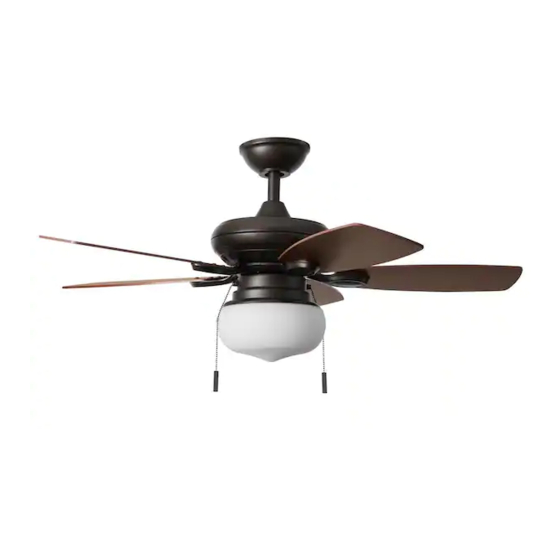
- Page 1 SKU/Model : #XXXX/#SW19129-A ORB #XXXX/#SW19129-A BN EMBRY HILLS LED 42 INCH CEILING FAN...
- Page 3 READ AND SAVE THESE INSTRUCTIONS.
- Page 4 We warrant the fan motor to be free from defects in workmanship and material present at time of shipment from the factory for a period of lifetime after the date of purchase by the original purchaser. And we warrant the LED light kit to be free from defects in workmanship and material present at time of shipment from the factory for a period of 3 years after the date of purchase by the original purchaser.
- Page 5 15+1 spare 15+1 spare Fiber washer Blade arm screw 10+1 spare Mounting plate screw (preassembled) Light kit plate screw (preassembled)
- Page 6 Blade arm Switch box Light kit plate 9W LED bulbs Glass shade...
- Page 8 Loosen the two set screws (II) from the coupling of the fan motor assembly (H)
- Page 9 Hanging the fan motor assembly to the mounting bracket...
- Page 11 Installing the canopy and canopy cover...
- Page 12 Fastening the blades to the blade arms Attach the fan blade (A) to the blade arm (I) by using the three blade screws (AA) and the three fiber washer (BB). Tighten all blade screws (AA) and fiber washers (BB) securely. Repeat same process for the other four blades (A).
- Page 13 Loose the five screws (QQ) and remove the five plastic blocks (RR) from the fan motor assembly (H) before attaching the blade arm (I) to the fan motor assembly (H). Discard the five screws (QQ) and the five plastic blocks (RR). Tighten the blade arm (I) onto the bottom of fan motor assembly (H) by using the two blade arm screws (CC).
- Page 14 Installing the switch box to the fan motor assembly Remove one of the screws (KK) from the mounting plate of the fan motor assembly (H) and loosen the other two screws (KK), but do not remove. While holding the switch box (J) under your fan, firmly snap the wire connector plugs (SS) together. Place the key holes from the switch box (J) over the two screws (KK) previously loosened from the fan motor assembly (H) .
- Page 15 Attaching the light kit plate to the the switch box CAUTION: To Reduce The Risk Of Electric Shock, Disconnect The Electrical Supply Circuit To The Fan Before Installing The Light Kit. Remove one of the screws (LL) from the switch box (J) and loosen the other two screws (LL), but do not remove. While holding the light kit plate (K) under your fan, snap the white connection plug from the switch box (J) to the white connection plug from the light kit plate (K).
- Page 16 Installing the LED bulbs Install the glass shade Attach the glass shade (M) to the light kit plate (K) by Install the 9W LED bulb (L) into the socket of twisting tightly. (DO NOT OVERTIGHTEN) the light kit plate (K).
- Page 17 Attach the pull chain fobs (MM) to the chain on the light kit plate (K). The 3-speed pull chain (UU) The light kit pull chain (VV) Reverse Function The reverse switch (WW) is located on the surface of the switch box (J). left right...
- Page 18 Balancing kit includes an additional instruction manual within the packet.
- Page 19 Fiber washer Flywheel screw Blade arm Switch box Light kit plate Mounting plate screw (preassembled) 9W LED bulbs Light kit plate screw (preassembled) Glass shade...
- Page 20 HAMPTON BAY CF542KP-01...
Need help?
Do you have a question about the SW19129-A ORB and is the answer not in the manual?
Questions and answers