Advertisement
Quick Links
SKU: #1009 462 365
Model: #SW22008GD
USE AND CARE GUIDE
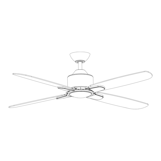
CHELIA LED 56 INCH CEILING FAN
THANK YOU
We appreciate the trust and confidence you have placed in Hampton Bay through the purchase of this celing fan. We strive to continually
create guality products designed to enhance your home. Visit us online to see our full line of products available for your home
improvement needs. Thank you for choosing Hampton Bay!
Advertisement

Related Manuals for HAMPTON BAY CHELIA SW22008GD


Summary of Contents for HAMPTON BAY CHELIA SW22008GD
- Page 1 THANK YOU We appreciate the trust and confidence you have placed in Hampton Bay through the purchase of this celing fan. We strive to continually create guality products designed to enhance your home. Visit us online to see our full line of products available for your home...
- Page 2 Table of Contents...
- Page 3 1167RYS-06 Summer Wind International Ltd.
- Page 4 or, at our option, gives 0.28 16.22 1969 56 in. 6.91 kg 9.43 kg 33.93 3160 1.36' (1.42 m) (15.2 lb) (20.75 lb) 0.53 63.21 4517...
- Page 5 1 set 3+1 spare Remote control cradle hardware pack (ST3.5*13mm screw -2pcs, 1 set ST3.0*18mm screw-2pcs, #6/32*13mm screw-2pcs, anchor -2pcs)
- Page 6 1.5V Blade arm Remote control Remote control cradle 1.5V Coupling...
- Page 7 UL Listed fuse electrical...
- Page 8 fan motor assembly coupling set screws (II).
- Page 9 Hanging the fan motor assembly to the mounting bracket (LL) (HH)
-
Page 10: Installing The Receiver
Installing the receiver Insert the receiver (K) into the mounting bracket (B) with the ventilated side facing down. Wires coming from the downrod and the wires coming from the power source need to be positioned on the same side when inserting the receiver through the mounting bracket. - Page 11 Optional NOTE: The 3-wire receiver will enable independent control of fan and light at the wall switch if house wiring Optional has separate household red and black power wires. Connect the white (neutral) wire from the ceiling to the white wire marked "AC IN N" from the receiver (K). Connect the black (hot) wire from the ceiling to the black wire marked "AC IN L FOR MOTOR SWITCH"...
- Page 12 Remove one screw (JJ) from the mounting bracket (B) and loosen the other screw (JJ) approximately 1/4 turn. (JJ) screw (JJ)
- Page 13 WARNING: Failure to properly seat the blades (A) on the blade arms (J) and engage in the locking mechanism (MM) could result in the fan blades (A) loosening and possibly falling. To install the blade to the blade arm: Mount the fan blade (A) to the blade arm (J) by aligning the three key-slot holes in the blade (A) with the three posts on the top of the blade arm (J).
- Page 14 (BB)
- Page 15 CAUTION: To reduce the risk of electric shock, disconnect the electrical supply circuit to the fan before installing the light kit. the switch box (OO)
- Page 16 SYNCING THE RECEIVER AND THE REMOTE CONTROL Install two 1.5V batteries (N) into the remote control. To prevent damage to the remote control, remove the batteries if not used for long periods of time. Restore power to the ceiling fan and test for proper operation. WARNING: Do not short-circuit, disassemble, heat up, connect improperly, or dispose of used batteries in fire.
- Page 17 REMOTE CONTROL OPERATING INSTRUCTIONS : Press and release this button to turn the fan and light on/off. Fan & Light ALL ON/OFF NOTE: The fan has memory function. It will resume the speed and light setting on the ceiling fan prior Fan ON/OFF to the power being turned off.
-
Page 18: Reverse Function
REVERSE FUNCTION Summer SUMMER MODE Winter WINTER MODE... - Page 19 INSTALLING THE REMOTE CONTROL CRADLE Option A: Remove wall plate screws, install the remote cradle to the spacer with hardware provided. Then screw the assembly into the toggle switch wall plate with hardware provided. Option B: Remove wall plate screws, install the remote cradle to the decorative switch wall plate with hardware provided. Option C: Screw the remote cradle into drywall with hardware provided, with or without anchors.
- Page 22 1.5V Coupling Blade arm Remote control cradle hardware pack (ST3.5*13mm screw -2pcs, ST3.0*18mm screw-2pcs, #6/32*13mm Remote control screw-2pcs, anchor -2pcs) Remote control cradle 1.5V...
- Page 23 HAMPTON BAY CF456KR-01...
Need help?
Do you have a question about the CHELIA SW22008GD and is the answer not in the manual?
Questions and answers