Table of Contents
Advertisement
Quick Links
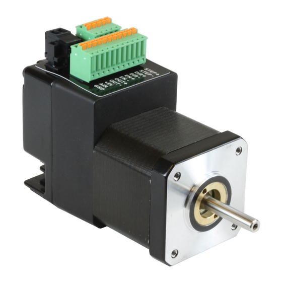
STM17
Hardware Manual
Re-Order from
Omegamation
1-888-55-66342
1-888-55-66342
1-888-55-OMEGA
omegamation.com
920-0034 rev A
9/30/2010
This datasheet has been downloaded from
Re-Order from
Omegamation
1-888-55-66342
1-888-55-66342
1-888-55-OMEGA
omegamation.com
TM
TM
http://www.digchip.com
at this
page
Advertisement
Table of Contents

Related Manuals for Applied Motion Products STM17 Series


Summary of Contents for Applied Motion Products STM17 Series
- Page 1 Re-Order from Omegamation 1-888-55-66342 1-888-55-66342 1-888-55-OMEGA omegamation.com STM17 Hardware Manual Re-Order from Omegamation 1-888-55-66342 1-888-55-66342 1-888-55-OMEGA omegamation.com 920-0034 rev A 9/30/2010 This datasheet has been downloaded from http://www.digchip.com at this page...
-
Page 2: Table Of Contents
The Digital Output ..........................................22 Reference Materials ..........................................23 Mechanical Outlines..........................................23 Technical Specifications ........................................24 Torque-Speed Curves ........................................26 Drive/Motor Heating ........................................... 30 Mating Connectors and Accessories ..................................32 LED Error Codes ............................................. 33 Contacting Applied Motion Products ..................................33... -
Page 3: Introduction
9/30/2010 Introduction Thank you for selecting the Applied Motion Products STM17 Drive+Motor. We hope our dedication to performance, quality and economy will make your motion control project successful. If there’ s anything we can do to improve our prod- ucts or help you use them better, please call or fax. We’d like to hear from you. Our phone number is (800) 525-1609, or you can reach us by fax at (831) 761-6544. -
Page 4: Block Diagram Stm17S, Stm17Q
920-0034 rev A STM17 Hardware Manual 9/30/2010 Block Diagram STM17S, STM17Q 12-48 VDC External 5 Volt DC Power Supply Power Supply RS-232 TX, RX, GND, +5V RS-232 or RS-485 RS-485 3.3VDC RX+, RX-, TX+, TX-, GND Internal Voltage Logic Temp Supply Det. -
Page 5: Block Diagram Stm17C
920-0034 rev A STM17 Hardware Manual 9/30/2010 Block Diagram STM17C 12-48 VDC External Power Supply 5 VDC Bit Rate Power Supply Node ID CANopen 3.3VDC Voltage To CANopen CAN2.0b Controller Power Temp Host Supply Monitor To PC RS-232 (for configuration) +5VDC (50mA MAX) MOSFET motor... -
Page 6: Safety Instructions
920-0034 rev A STM17 Hardware Manual 9/30/2010 Safety Instructions Only qualified personnel are permitted to transport, assemble, commission, and maintain this equipment. Properly quali- fied personnel are persons who are familiar with the transport, assembly, installation, commissioning and operation of motors, and who have the appropriate qualifications for their jobs. -
Page 7: Getting Started
• Install the ST Configurator software from the CD. • Launch the software by clicking Start...Programs...Applied Motion Products. • Connect the drive to the PC using the programming cable. When using RS-422/485, the drive must be set up in a 4-Wire configuration (see “Connecting to a host using RS-422/485”.) -
Page 8: Choosing A Power Supply
920-0034 rev A STM17 Hardware Manual 9/30/2010 Choosing a Power Supply The main considerations when choosing a power supply are the voltage and current requirements for the application. Voltage Selection The STM17 is designed to give optimum performance between 12 and 48 Volts DC. Choosing the voltage depends on the performance needed and motor/drive heating that is acceptable and/or does not cause a drive over-temperature. - Page 9 920-0034 rev A STM17 Hardware Manual 9/30/2010 STM17S-2AN Wattage vs Speed 12V Watts 1.8 Amps @ Ambient of 40°C 24V Watts 80 x 80x 6(mm) Aluminum Plate 48V Watts Speed(RPS) 12V Watts STM17S-3AN Wattage vs Speed 24V Watts 1.8 Amps @ Ambient of 40°C 48V Watts 80 x 80x 6(mm) Aluminum Plate Speed(RPS)
-
Page 10: Current Selection
920-0034 rev A STM17 Hardware Manual 9/30/2010 Current Selection The maximum supply currents required by the STM17 are shown in the charts below at different power supply voltage inputs. The STM17 power supply current is lower than the winding currents because it uses switching amplifiers to con- vert a high voltage and low current into lower voltage and higher current. - Page 11 920-0034 rev A STM17 Hardware Manual 9/30/2010 STM17X-2 STM17X-2 STM17X-3 STM17X-3...
-
Page 12: Installation/Connections
920-0034 rev A STM17 Hardware Manual 9/30/2010 Installation/Connections Connecting the Power Supply Connect the power supply “+” terminal to the drive “+” terminal and the power supply “-” terminal to the drive “-” termi- nal using 16 to 20-gauge wire. The STM17 contains an internal fuse connected to the “+” terminal. This fuse is not user replaceable. -
Page 13: Connecting The Stm17 Communications
920-0034 rev A STM17 Hardware Manual 9/30/2010 Connecting the STM17 Communications The STM17 is available with two types of serial communications, RS-232 (STM17x-xAx) or RS-422/485 (STM17x-xRx). Each type requires a different hardware connection for interface to a PC or other host system. The RS-232 version comes with a cable that will provide the interface to an RS-232 port through a DB9 style connector. -
Page 14: Four-Wire Configuration
920-0034 rev A STM17 Hardware Manual 9/30/2010 GND (circuit ground) RS-422/485 Connector diagram Four-Wire Configuration Four-wire Systems utilize separate transmit and receive wires. One pair of wires must connect the host’ s transmit signals to each drive’ s RX+ and RX- terminals. The other pair connects the drive’ s TX+ and TX- terminals to the host’ s receive signals. A logic ground terminal is provided on each drive and can be used to keep all drives at the same ground potential. -
Page 15: Two-Wire Configuration
920-0034 rev A STM17 Hardware Manual 9/30/2010 Two-Wire Configuration GND (circuit ground) RS-422/485 Connector diagram to Host GND to Host Tx- (A) to Host Tx+ (B) +Rx- +Tx- GND +Rx- +Tx- GND +Rx- +Tx- GND Drive 1 Drive 2 Drive n Typical RS-422/485 Two-Wire System Transmit and receive on the same pair of wires can lead to trouble. -
Page 16: Connecting To An Stm17 Using Usb
920-0034 rev A STM17 Hardware Manual 9/30/2010 sure that each drive on your network has a unique address. If you are using a 2-wire network, you may need to set the Transmit Delay, too. 10 milliseconds works on the adapters we’ve tried. Once you’ve made your choices, click Download to save the settings to your drive. -
Page 17: Stm17 Inputs And Outputs
920-0034 rev A STM17 Hardware Manual 9/30/2010 STM17 Inputs and Outputs All STM drive+motors include three digital inputs, one analog input, and one digital output. • STEP & DIR: 5 to 24 volt digital input signals for commanding position. When not being used for the Step & Direc- tion function, these inputs can be used for CW & CCW Limit, CW & CCW Jogging and Run/Stop & Direction Velocity modes. -
Page 18: The Step (Step) And Direction (Dir) Inputs
920-0034 rev A STM17 Hardware Manual 9/30/2010 The Step (STEP) and Direction (DIR) Inputs The STM17 drive+motors include two high-speed inputs called STEP and DIR. They accept 5 to 24 volt single-ended or differential signals, up to 2 MHz. Typically these inputs connect to an external controller that provides step & direction command signals. - Page 19 920-0034 rev A STM17 Hardware Manual 9/30/2010 STEP+ STEP- Master STM17 Encoder DIR+ DIR- Wiring for Encoder Following DIR+ 5 to 24 direction switch DIR- STM17 Power run/stop switch STEP+ Supply (closed=run) STEP- Using Mechanical Switches...
-
Page 20: The Enable (En) Digital Input
920-0034 rev A STM17 Hardware Manual 9/30/2010 The Enable (EN) Digital Input As mentioned in the previous section, the high-speed STEP and DIR inputs are designed for high speed op- eration. The Enable digital input is designed for low speed digital input operation between 5 and 24 volts DC. Note: If current is flowing into or out of an input, the logic state of that input is low or closed. -
Page 21: The Analog Input
920-0034 rev A STM17 Hardware Manual 9/30/2010 The Analog (AIN) Input inside drive The STM17 drives feature an analog input. The input can accept a signal 50ma Limit range of 0 to 5 VDC. The drive can be configured to operate at a speed or position that is proportional to the analog signal. -
Page 22: The Digital Output
920-0034 rev A STM17 Hardware Manual 9/30/2010 The Digital Output The STM17 drives feature one optically isolated digital output. This output can be set to automatically con- trol a motor brake, to signal a fault condition, to indicate when the motor is moving or to provide an output frequency proportional to motor speed (tach signal). -
Page 23: Reference Materials
920-0034 rev A STM17 Hardware Manual 9/30/2010 Reference Materials Mechanical Outlines L±1 42.3 MAX 4-M3Depth 4.5 Ø 22 55.8 42.3 MAX Ø 5 4.50 Flat 43.5 42.4 Model Length (L) in mm STM17x-1 STM17x-2 72.5 STM17x-3... -
Page 24: Technical Specifications
920-0034 rev A STM17 Hardware Manual 9/30/2010 Technical Specifications Power AmPlifier Amplifier Type Dual H-Bridge, 4 Quadrant Current Control 4 state PWM at 16 KHz Output Torque STM17x-1x Series – to 31 oz-in with suitable power supply STM17x-2x Series – to 54 oz-in with suitable power supply STM17x-3x Series –... -
Page 25: Inputs And Outputs
920-0034 rev A STM17 Hardware Manual 9/30/2010 Multiple Modes Of Control Pulse Input - Step & Direction, CW/CCW, A/B Quadrature (incre- mental encoder Velocity - Analog Velocity, Switch Control Velocity, Serial Command- ed Velocity Serial Command Language (SCL) Stored Program Execution (Q models only) Noise Filtering Programmable hardware digital noise filter, software noise filter Encoder Feedback... -
Page 26: Torque-Speed Curves
920-0034 rev A STM17 Hardware Manual 9/30/2010 PHYsiCAl & enVironmentAl Mass STM17x-1xx: 292 g (10.3 oz) STM17x-2xx: 360 g (12.7 oz) STM17x-3xx: 441 g (15.6 oz) Rotor Inertia STM17x-1xx: 38 g-cm (0.21 oz-in STM17x-2xx: 57 g-cm (0.31 oz-in STM17x-3xx: 82 g-cm (0.45 oz-in Ambient Temperature 0-40°C (32-104°F) when mounted to a suitable heatsink... - Page 27 920-0034 rev A STM17 Hardware Manual 9/30/2010 STM17X-2 STM17X-2 STM17X-3 STM17X-3...
-
Page 28: Drive/Motor Heating
920-0034 rev A STM17 Hardware Manual 9/30/2010 Drive/Motor Heating Step motors convert electrical power from the driver into mechanical power to move a load. Because step motors are not perfectly efficient, some of the electrical power turns into heat on its way through the motor. This heating is not so much dependent on the load being driven but rather the motor speed and power supply voltage. - Page 29 920-0034 rev A STM17 Hardware Manual 9/30/2010 12V Temp 12V Duty Cycle STM17S-2AN Temperature vs. Speed STM17S-2AN Max Duty Cycle vs Speed 24V Temp 24V Duty Cycle 1.8 Amps @ Ambient of 40°C 1.8 Amps @ Ambient of 40°C 48V Temp 80 x 80x 6(mm) Aluminum Plate 48V Duty Cycle 80 x 80x 6(mm) Aluminum Plate...
-
Page 30: Mating Connectors And Accessories
920-0034 rev A STM17 Hardware Manual 9/30/2010 Mating Connectors and Accessories Mating Connector (Type) PArt no DC Power (2-position, screw terminal) Weidmuller 1615780000 I/O (11-position, spring cage) Phoenix 1881419 Comm (5-position, spring cage) Phoenix 1881354 Accessories USB-Serial Adapter with one RS-232 port and one RS-485 port for programming all units: P/N 8500-003 DC Power Supplies: 24V, 50W switching power supply, P/N PS50A24 24 V, 150W switching power supply, P/N PS150A24... -
Page 31: Contacting Applied Motion Products
5 red, 1 green over current / short circuit 6 red, 1 green open motor winding 7 red, 1 green serial communication error Contacting Applied Motion Products Corporate Headquarters 404 Westridge Drive Re-Order from Omegamation Watsonville, CA 95076 (831) 761-6555...
Need help?
Do you have a question about the STM17 Series and is the answer not in the manual?
Questions and answers