
Related Manuals for Applied Motion Products PDO 2035


Summary of Contents for Applied Motion Products PDO 2035
- Page 1 sales@artisantg.com artisantg.com (217) 352-9330 | Visit our website - Click HERE...
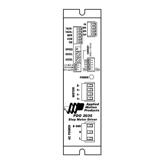
- Page 2 User's Manual PDO 2035 Step Motor Driver TACH- TACH+ STEP SPEED DECEL ACCEL 1000 BYPASS HALF FULL STEP STEP POWER B– A– PDO 2035 Step Motor Driver motors • drives • controls...
- Page 3 Do I Have the Right Manual? In April, 1999 we began shipping PDO 2035 drives. Prior to that, we made a similar drive called the PD2035. The PDO 2035, which is the subject of this manual, sports the following improvements: •...
-
Page 4: Block Diagram
Introduction Thank you for selecting an Applied Motion Products motor control. We hope our dedication to performance, quality and economy will make your motion control project successful. If there's anything we can do to improve our products or help you use them better, please call or fax. -
Page 5: Getting Started
Getting Started To use your Applied Motion Products motor control, you will need the following: • an AC power cord • 5-24 volts DC to activate the optoisolation circuits • a source of step pulses • if your application calls for bidirectional rotation, you'll also need a direction signal •... - Page 6 The PDO 2035 is set for 110 volt operation at the factory. All you need to do is install a power cord and plug it in. If you want to direct wire the PDO 2035 to AC power, you must consult a qualified electrician and observe all building and electrical codes.
-
Page 7: Connecting The Motor
Always unplug the line cord from the wall before attaching it to the PDO 2035 •Connect the black or brown wire to the PDO 2035 "L" terminal of the AC power connector. That is the line, or "hot" connection. •Connect the white or blue wire to neutral. That's the "N" terminal. - Page 8 Eight lead motors can also be connected in two ways: series and parallel. As with six lead motors, series operation gives you more torque at low speeds and less torque at high speeds. In series operation, the motor should be operated at 30% less than the rated current to prevent over heating.
- Page 9 If you are using 5 volt logic (TTL level) then each signal must sink 5 mA. Inside PDO 2035 If your STEP, DIR and ENABLE signals are sinking (NPN) then connect COM to your power supply +. If your signals are sourcing (PNP) then connect COM to power supply -.
- Page 10 Using the TACH Output The PDO2035 has a pulse output to tell you how fast the oscillator is going. It produces one pulse per motor step. You can connect this to a counter to provide position information, or to a tachometer to provide speed data, or both. The pulse output is optically isolated for noise immunity, which makes it more flexible and more reliable, but also harder to hookup.
-
Page 11: Using The Oscillator
Using the Oscillator The PDO2035 is equipped with an internal pulse generator that you can use to control the motor. To BYPASS select the oscillator mode of operation (run/stop mode) move switch 2 away from the BYPASS label, as shown at the right. -
Page 12: Setting Phase Current
Using the Oscillator with Switches & PLCs. If you plan to use the PDO 2035 in oscillator mode, you may need a source of voltage to activate the optoisolation circuits. This is true if you are using mechanical switches or relays. It may also be the case if you are using a PLC with optically isolated outputs, since they behave like switches. -
Page 13: Current Setting Table
Current Setting Table 1000 1000 .125 1.125 AMPS/PHASE AMPS/PHASE 1000 1000 1.25 AMPS/PHASE AMPS/PHASE 1000 1000 .375 1.375 AMPS/PHASE AMPS/PHASE 1000 1000 AMPS/PHASE AMPS/PHASE 1000 1000 .625 1.625 AMPS/PHASE AMPS/PHASE 1000 1000 1.75 AMPS/PHASE AMPS/PHASE 1000 1000 .875 1.875 AMPS/PHASE AMPS/PHASE 1000 1000... -
Page 14: You Will Need
Using Remote Speed Control Potentiometer The PDO 2035 step motor driver includes an analog signal input connector that can be used to control the oscillator speed externally. Normally, an on board potentiometer controls the speed. Whether you use the on-board or external pots, the accel/decel ramping remains active. -
Page 15: Mounting The Drive
Mounting the Drive You should mount the PDO 2035 on the heat transfer plate as shown below. Use #8 or #10 screws. The amplifiers in the drive generate heat. Unless you are running at 1 amp or below, you may need a heat sink. To operate the PDO 2035 continuously at maximum power you must properly mount it on a heat sinking surface with a thermal constant of no more than 4°C/watt. -
Page 16: Technical Specifications
Technical Specifications Amplifiers Dual, bipolar recirculating H-bridge, pulse width modulated switching at 20 kHz. 0.125 - 2.0 amps/phase output current, switch selectable in 0.125 A increments. 50 watts maximum output power. Automatic idle current reduction, reduces current to 50% of setting after one second. -
Page 17: Mechanical Outline
DECEL ACCEL 1000 BYPASS HALF FULL STEP STEP POWER 6.00" 6.80" B– A– PDO 2035 Step Motor Driver 1.75" .273" Copyright 2000 Applied Motion Products, Inc. 404 Westridge Drive Watsonville, CA 95076 Tel (831) 761-6555 (800) 525-1609 Fax (831) 761-6544...
Need help?
Do you have a question about the PDO 2035 and is the answer not in the manual?
Questions and answers