Table of Contents
Advertisement
Quick Links
Hardware Manual
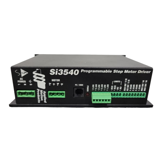
Si3540
Programmable Step Motor Driver
IN 5/JOG CW
IN 6 JOG CCW
INPUT COM
INPUT COM
INPUT 1
INPUT 2
INPUT 3
INPUT 4
CW +
CW -
CCW +
CCW -
OUT 1 +
OUT 1 -
OUT 2 +
OUT 2 -
OUT 3 +
OUT 3 -
POWER
B-
B+
A-
A+
G
N
L
motors • drives • controls
-1-
Table of Contents
Introduction --------------------------------------------------------------------- 3
Features -------------------------------------------------------------------------- 3
Block Diagram ------------------------------------------------------------------- 3
Getting Started ------------------------------------------------------------------ 4
Connecting the AC Line --------------------------------------------------------- 5
Connecting the Motor ----------------------------------------------------------- 7
Connecting to the PC ------------------------------------------------------------ 8
Jogging -------------------------------------------------------------------------- 9
Limit Switches ------------------------------------------------------------------ 9
Wiring a Mechanical Limit Switch --------------------------------------------- 10
Wiring a Limit Sensor ---------------------------------------------------------- 10
Wiring Inputs ------------------------------------------------------------------- 11
Wiring Outputs ----------------------------------------------------------------- 13
Microstepping ------------------------------------------------------------------ 14
Mounting the Drive ------------------------------------------------------------- 15
Mounting the Optional MMI --------------------------------------------------- 15
Recommended Motors ---------------------------------------------------------- 17
Mechanical Outline ------------------------------------------------------------- 17
Technical Specifications -------------------------------------------------------- 18
Mechanical Outline - Optional MMI ------------------------------------------- 19
Re-Order from
Omegamation
1-888-55-66342
1-888-55-66342
1-888-55-OMEGA
omegamation.com
TM
Omegamation
Re-Order from
TM
1-888-55-66342
1-888-55-66342
1-888-55-OMEGA
omegamation.com
-2-
Advertisement
Table of Contents

Related Manuals for Applied Motion Products Si3540


Summary of Contents for Applied Motion Products Si3540
-
Page 1: Table Of Contents
Table of Contents Hardware Manual Introduction --------------------------------------------------------------------- 3 Features -------------------------------------------------------------------------- 3 Block Diagram ------------------------------------------------------------------- 3 Si3540 Getting Started ------------------------------------------------------------------ 4 Connecting the AC Line --------------------------------------------------------- 5 Programmable Step Motor Driver Connecting the Motor ----------------------------------------------------------- 7 Connecting to the PC ------------------------------------------------------------ 8... -
Page 2: Introduction
Introduction Getting Started Thank you for selecting an Applied Motion Products motor control. We hope our To use your Si3540 motor control, you will need the following: dedication to performance, quality and economy will make your motion control a power cable (line cord) project successful. -
Page 3: Connecting The Ac Line
Remove about 5 mm (3/16 inces) of insulation from each of the three wires of your The Si3540 is set for 110 VAC operation at the factory. If you use 110 VAC power, line cord. (That’s right, three wires. For safety, always use a three wire power cord all you need to do is install a power cord and plug it in. -
Page 4: Connecting The Motor
Note: NC means not connected to anything. COM2 port for the Si3540. On some PCs, COM2 will have a 25 pin connector that does not fit the black adapter plug. If this is the case, and you must use COM2,... -
Page 5: Jogging
In that case, wire the sensor this way: sensors that may be far from the Si3540 with less risk of intoducing noise to the Si3540. The schematic diagram of the limit switch input circuit is shown below. -
Page 6: Wiring Inputs
OUT– and MC8400 indexer-drives. Note: If current is flowing into or out of an Si3540 input, the logic state of that Connecting a 3540i, Si5580, 7080i or MC8400 input is low. If no current is flowing, or the input is not connected, the logic state (When output closes, Si3540 input goes low). -
Page 7: Wiring Outputs
Schematic Diagram of Si3540 Output Circuit Since there is no electrical conneciton to the Si3540, you must provide the source of current and voltage, typically from a power supply. You must also limit the current to less than 100 mA so that the output transistor is not damaged. You would normally use a resistor for this, but some loads (such as PLC inputs) limit the current automatically. -
Page 8: Mounting The Drive
MMI. If this is the case, you will need to use some kind of sealant and you need to reprogram the Si3540, you can use any telephone line cord as a Y E S to keep dust and liquid out. -
Page 9: Recommended Motors
Recommended Motors Technical Specifications Motor Size Winding Max Torque Current Amplifiers Dual, MOSFET H-bridge, 3 state, pulse width modulated (PWM) Number inches Connection oz-in Amps switching at 20 kHz. 0.2 - 3.5 amps/phase output current, software 5014-842 1.38 x 1.38 x 1.57 4 lead selectable. -
Page 10: Mechanical Outline - Optional Mmi
11/2/99 Mechanical Outline - Optional MMI Applied Motion Products, Inc. 404 Westridge Drive Watsonville, CA 95076 Tel (831) 761-6555 (800) 525-1609 Fax (831)-761-6544 http://www.applied-motion.com Copyright 1999 -19- -20-...
Need help?
Do you have a question about the Si3540 and is the answer not in the manual?
Questions and answers