Table of Contents
Advertisement
Quick Links
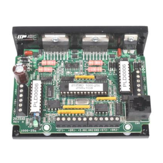
Mechanical Outline
1.50"
0.125"
2x Ø.125
3.70"
0.25"
0.15"
.875"
Connector Layout
VDC+
VDC-
A+
A-
B+
B-
axis 1
Applied Motion Products, Inc.
404 Westridge Drive Watsonville, CA 95076
Tel (831) 761-6555
(800) 525-1609
SHOP ONLINE at www.airlinehyd.com
2.50"
3.75"
4.00"
0.25"
3.00"
A+
A-
B+
B-
OUT+
OUT-
axis 2
Fax (831) 761-6544
4x Ø.125
Two Axis Step Motor Drive
6/4/03
JK
User's Manual
2035XD
motors • drives • controls
800-999-7378
Advertisement
Table of Contents

Related Manuals for Applied Motion Products 2035XD


Summary of Contents for Applied Motion Products 2035XD
- Page 1 .875" 6/4/03 Connector Layout VDC+ OUT+ VDC- OUT- axis 1 axis 2 Applied Motion Products, Inc. 404 Westridge Drive Watsonville, CA 95076 motors • drives • controls Tel (831) 761-6555 (800) 525-1609 Fax (831) 761-6544 SHOP ONLINE at www.airlinehyd.com 800-999-7378...
- Page 2 Technical Specifications Amplifiers Dual, bipolar H-bridge, pulse width modulated three state switch- ing at 20.5kHz. 12-35 VDC input. 0.1 - 2.0 amps/phase output current, software selectable. 70 watts maximum output power per axis. Automatic idle current reduction (software selectable), reduces current when motor is not moving. Digital Inputs Step/run 1, step/run 2, direction 1, direction 2.
- Page 3 Mounting the Drive Contents You can mount your drive on the wide or the narrow side of the chassis. If you Introduction ....................... 4 mount the drive on the wide side, use #4 screws through the four corner holes. For Features ........................
- Page 4 Introduction Choosing a Power Supply Thank you for selecting an Applied Motion Products motor control. We hope our Voltage Voltage Voltage Voltage Voltage dedication to performance, quality and economy will make your motion control Chopper drives work by switching the voltage to the motor terminals on and off project successful.
- Page 5 • a small flat blade screwdriver for tightening the connectors (included with drive). ing the steps even further. The 2035XD offers a choice of full step, half step and 13 • a personal computer running Microsoft Windows 95, 98, NT, Me, 2000 or XP.
- Page 6 Connect the motor power supply "+" terminal to the driver terminal labeled "+ VDC". Connect power supply "-" to the drive terminal labeled "VDC-". Use no inside 2035XD smaller than 20 gauge wire. Be careful not to reverse the wires. Reverse connection OUT1+ will destroy your driver, void your warranty and generally wreck your day.
- Page 7 8 Leads Series Connected 8 Leads Parallel Connected below. Connecting Logic 220Ω inside 2035XD STEP+ The 2035XD contains optical isolation circuitry to STEP+ prevent the electrical noise inherent in switching DIR+ run/stop switch amplifiers from interfering with your circuits. (closed=run) 5 VDC 220Ω...
- Page 8 Step and Direction Signals Run/Stop Signals Most PLCs, don't use 5 volt logic. You can connect signal levels as high as 24 volts to the 2035XD if you add external dropping resistors to the STEP and DIR +5V OUT DIR+ Indexer inputs, as shown below.
Need help?
Do you have a question about the 2035XD and is the answer not in the manual?
Questions and answers