Table of Contents
Advertisement
Quick Links
Advertisement
Table of Contents

Related Manuals for Applied Motion Products STR2M


Summary of Contents for Applied Motion Products STR2M
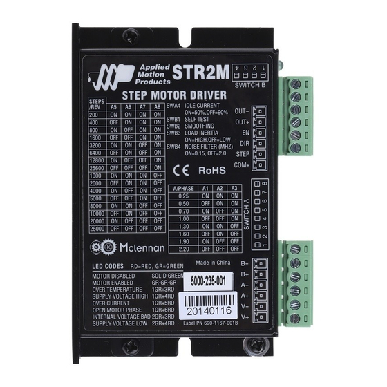
- Page 1 Hardware Manual 5000-235-001 STR2M Step Motor Drive 920-0067A 1/10/2013...
-
Page 2: Table Of Contents
920-0067A 5000-235-001 STR2M 1/10/2013 Contents Safety Instructions ............................................. 3 Introduction ................................................5 Features ..................................................5 Block Diagram ............................................... 6 Getting Started ..............................................7 Mounting the Drive ............................................8 Connecting the Power Supply ........................................8 Choosing a Power Supply........................................... 10 Voltage ................................................. 10 Current ................................................. -
Page 3: Safety Instructions
• It is vital to ensure that all system components are connected to earth ground. Electrical safety is impossible without a low-resistance earth connection. • The STR2M contains electrostatically sensitive components that can be damaged by incorrect handling. Discharge yourself before touching the product. Avoid contact with high insulating materials (artificial fabrics, plastic film, etc.). - Page 4 920-0067A 5000-235-001 STR2M 1/10/2013 • In operation, depending on the degree of enclosure protection, the product can have bare components that are live or have hot surfaces. Control and power cables can carry a high volt- age even when the motor is not rotating.
-
Page 5: Introduction
1/10/2013 Introduction Thank you for selecting an Applied Motion Products motor control. We hope our dedication to performance, quality and economy will make your motion control project successful. If there’ s anything we can do to improve our products or help you use them better, please call or fax. -
Page 6: Block Diagram
920-0067A 5000-235-001 STR2M 1/10/2013 Block Diagram 12-48 VDC from external power supply 3.3/5/15V Regulators Voltage Sensors Status LEDs motor AMPLIFIER STEP Optical Digital Isolation Filter Overcurrent Sensors 5,6,7,8=steps/rev Optical 4=idle current Isolation 1,2,3=run current 4=step noise filter 3=load inertia Step Pulse Type... -
Page 7: Getting Started
5000-235-001 STR2M 1/10/2013 Getting Started To use your STR2M step motor drive, you’ll need the following: • a 12 to 48 volt DC power supply. Please read the section Choosing a Power Supply for help in choosing the right power supply. -
Page 8: Mounting The Drive
Use 18 or 20 gauge wire. The STR2M drive contains an internal fuse that connects to the power supply + terminal. This fuse is not user replaceable. If you want to install a user serviceable fuse in your system install a fast acting 3 amp fuse in line with the + power supply lead. - Page 9 920-0067A 5000-235-001 STR2M 1/10/2013 Power Supply and Ground Connections Locate fuse in-line with “+” connection If you plan to use a regulated power supply you may encounter a problem with regeneration. If you rapidly decelerate a load from a high speed, much of the kinetic energy of that load is transferred back to the power supply.
-
Page 10: Choosing A Power Supply
That’ s because the STR2M uses a switching amplifier, converting a high voltage and low current into lower voltage and higher current. The more the power supply voltage ex- ceeds the motor voltage, the less current you’ll need from the power supply. -
Page 11: Multiple Drives Sharing One Power Supply
The tables below and on the net page list the maximum current required for each motor at sev- eral common power supply voltages. Please consider this information when choosing a power supply. Table 1: STR2M Power Supply Current All motors connected as indicated. Max Power Supply Current (A) -
Page 12: System Wiring Recommendations
920-0067A 5000-235-001 STR2M 1/10/2013 Regeneration If you plan to use a regulated power supply you may encounter a problem with regeneration. If you rapidly decelerate a load from a high speed, much of the kinetic energy of that load is transferred back to the power supply. -
Page 13: Connecting The Motor
920-0067A 5000-235-001 STR2M 1/10/2013 Connecting the Motor Never connect or disconnect the motor while the power is on. If the motor has a shield or grounding wire, please connect it to the chassis ground screw located on the chassis near the motor-power connector. -
Page 14: Connecting Input Signals
5000-235-001 STR2M 1/10/2013 Connecting Input Signals The STR2M drive has three inputs: • STEP: a high speed digital input for step pulse commands, 5-24 volt logic • DIR: a high speed digital input for the direction signal, 5-24 volt logic •... -
Page 15: Connection Examples: En
920-0067A 5000-235-001 STR2M 1/10/2013 Connection Examples: EN COM+ 5-24 STR2M switch or relay Power (closed=logic low) Supply Connecting an Input to a Switch or Relay 5-24 COM+ Si drive STR2M Power OUT+ Supply OUT– Connecting another drive to EN (When output closes, input closes) -
Page 16: Fault Output
920-0067A 5000-235-001 STR2M 1/10/2013 FAULT Output The STR2M features a digital FAULT output. This output closes to FAULT+ signal a fault condition. FAULT- This output can be used to drive LEDs, relays and the inputs of other electronic devices like PLCs. The “+” (collector) and “-” (emitter) terminals of the output transistor are available at the connector. -
Page 17: Configuring The Drive
920-0067A 5000-235-001 STR2M 1/10/2013 Configuring the Drive Step 1: Setting the Current To select a current, simply move switches A1, A2 and A3 to the setting that corresponds to the motor of your choice. You can do this while power is on, but it is safer to select the motor before applying power to the drive so that you do not risk applying too much current to your motor. -
Page 18: Step 2: Setting Idle Current
In such cases, the idle current can be set to 90% as shown below. The idle current switch is located in switch bank A, on the front of the STR2M Step 3: Load Inertia The STR2M drives include anti-resonance and electronic damping features which greatly improve motor performance. -
Page 19: Step 4: Step Size
1/10/2013 Step 4: Step Size The STR2M requires a source of step pulses to command motion. This may be a PLC, an indexer, a motion controller or another type of device. The only requirement is that the device be able to produce step pulses whose frequency is in proportion to the desired motor speed, and be able to smoothly ramp the step speed up and down to produce smooth motor accel- eration and deceleration. - Page 20 920-0067A 5000-235-001 STR2M 1/10/2013 STEPS/REV 1600 3200 6400 12800 25600 1000 2000 4000 5000 8000 10000 20000 25000...
-
Page 21: Step 5: Step Pulse Type
STEP and DIR inputs. There are two settings for this filter: 150 kHz works well for most applications,. If you are operating the STR2M at a high number of steps/rev and at high motor speeds, you will be commanding the drive at step rates above 150 kHz. In such cases, you should use the 2 MHz setting as shown below. -
Page 22: Self Test
920-0067A 5000-235-001 STR2M 1/10/2013 Your maximum pulse rate will be the highest motor speed times the steps/rev. For example, 40 revs/second at 20,000 steps/rev is 40 x 20,000 = 800 kHz. Please consider this when deciding if you must increase the filter frequency. -
Page 23: Drive Heating
1/10/2013 Drive Heating While STR2M drivers efficiently transmit power between the power supply and motor, they do generate some heat in the process. This will cause the temperature of the drive to rise above the surrounding air temperature and may also require that the drive be mounted to a heat conducting metal surface. -
Page 24: Mechanical Outline
920-0067A 5000-235-001 STR2M 1/10/2013 Mechanical Outline... -
Page 25: Technical Specifications
920-0067A 5000-235-001 STR2M 1/10/2013 Technical Specifications Amplifier Digital MOSFET. 16 kHz PWM. Suitable for driving two phase step motors with four, six or eight leads. Protection against over-voltage, under-voltage, over-temp, and short circuit. Supply voltage: 12-48 VDC Under voltage alarm: 10 VDC... -
Page 26: Mating Connectors And Accessories
920-0067A 5000-235-001 STR2M 1/10/2013 Mating Connectors and Accessories Mating Connectors Motor/power supply: Phoenix Contact 1803617, included with drive. Signals: Phoenix Contact 1840405, included with drive. Accessories Regeneration Clamp: Applied Motion Products RC-050. -
Page 27: Alarm Codes
Alarm Codes In the event of a drive fault or alarm, the green LED will flash one or two times, followed by a series of red flashes. The pat- tern repeats until the alarm is cleared. Code Error solid green no alarm, motor disabled flashing green no alarm, motor enabled 1 green, 3 red over temperature...
Need help?
Do you have a question about the STR2M and is the answer not in the manual?
Questions and answers