Estun ERC3-C1 Series Operating Instructions Manual
Robot control cabinet
Hide thumbs
Also See for ERC3-C1 Series:
- Operation instructions manual (49 pages) ,
- Operation manual (99 pages)
Table of Contents
Advertisement
Quick Links
Advertisement
Table of Contents

Related Manuals for Estun ERC3-C1 Series


Summary of Contents for Estun ERC3-C1 Series
- Page 1 ESTUN Robot ERC3-C1 Series CE Version Control Cabinet Operation Manual...
- Page 2 ESTUN Robot ERC3-C1 Series CE Version Control Cabinet Operation Manual ECM04401-EN-...
- Page 3 Thank you for purchasing ESTUN robots. Before using the robot, be sure to read the SAFETY PRECAUTION and understand the content. ESTUN is committed to prove the products. All specifications and designs are subject to change without notice. All statements, information, and advice provided in this manual have been carefully processed, but no guarantee is given for their complete accuracy.
-
Page 4: Foreword
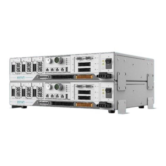
Foreword This manual explains the usage of the ERC3-C1 control cabinet. The ERC3-C1 is a compact control cabinet. The compatible robot types for this control cabinet are as follows: Cabinet Model Compatible Models ER3-400-SR-CE ER3-500-SR-CE ER6-500-SR-CE ER6-600-SR-CE ER6-700-SR-CE ER10-500-SR-CE ERC3-C1-X1A4-INT ER10-600-SR-CE ER10-600-SR/LI-CE ER10-700-SR-CE... -
Page 5: Revision History
Revision History Revision Date Content 2024.08 Initial release. -
Page 6: Safety Precautions
We will not assume any legal liability for personal safety incidents or property losses resulting from improper product operation. Companies or individuals using ESTUN Robots should familiarize themselves with the standards and laws in their respective regions or countries. Additionally, appropriate safety measures should be installed to protect personnel using the robot. -
Page 7: Safety Precautions
Do not install if the received product does not match the model, quantity, or name listed on the product list! ⚫ If any of these or other issues are found, do not attempt to install the product yourself! Please contact ESTUN staff promptly. - Page 8 When using professional equipment for handling, ensure no personnel are beneath the equipment to avoid injury from falling objects. ⚫ Follow ESTUN's recommended methods for handling and installing the robot. Incorrect methods may cause the robot to topple, and lead to accidents. Installation precautions ⚫...
-
Page 9: Precautions For Maintenance
⚫ After powering on, check all E-stop switches. If any are not functioning properly, stop using the equipment immediately and contact ESTUN support. ⚫ It is strictly prohibited to replace or dismantle any equipment components while the power is on, as there is a risk of electric shock. -
Page 10: Other Safety Precautions
Other safety precautions: ⚫ All operators, maintenance personnel, and users must receive professional training and strictly follow product usage guidelines and safety precautions. ⚫ Appropriate safety gear, such as helmets, safety shoes, and suitable work clothing, must be worn by all users and operators. ⚫... -
Page 11: Security Category
Accessory Safety Category Emergency Protective Routine Control cabinet model Applicable standards stop Stop EN/ISO 13849-1:2008 Cat.3 Cat.3 ERC3-C1 Series CE Versions standard PL d PL d control cabinet EN 954-1:1996 SIL 2 SIL 2... - Page 12 (as shown in Table 1-1 above). E-Stop Functional Description The ESTUN robot has the following emergency stop devices, the specific emergency stop button location for the ERC3-C1 series certified version of the control cabinet is located on the oscillator as shown below. E-stop Button Schematic When the emergency stop button is pressed, the robot stops immediately.
- Page 13 If the robot is to be stopped by an external device using the safety stop function, install the emergency stop button in an appropriate location within the operator's reach according to the system layout. Tapping the Emergency Stop means disconnecting the power source to the motors on the robot.
- Page 14 0.322 0.287 0.175 0.286 Stopping time (s) Slip distance (°) 63.411 96.815 70.08 219.36 Robot Model ER6-700-SR-CE E-Stop axis number 0.456 0.35 0.192 0.279 Stopping time (s) 90.699 111.66 83.196 213.4178 Slip distance (°) Robot Model ER10-500-SR-CE E-Stop axis number 0.364 0.268 0.204...
- Page 15 63.254 134.446 38.279 124.388 Slip distance (°) Robot Model ER20-800-SR-HI-CE E-Stop axis number 0.479 0.335 0.271 0.355 Stopping time (s) Slip distance (°) 85.137 73.553 185.387 166.26 Robot Model ER20-1000-SR-HI-CE E-Stop axis number 0.599 0.392 0.348 0.396 Stopping time (s) 95.132 99.281 256.887...
- Page 16 Robot Model ER7-910-MI-CE E-Stop axis number 0.252 0.344 0.316 0.28 0.332 0.315 Stopping time (s) 37.482 54.788 69.286 76.457 52.939 120.017 Slip distance (°) Robot Model ER10B-900-MI-CE E-Stop axis number 0.483 0.544 0.360 0.298 0.292 0.335 Stopping time (s) Slip distance (°) 61.785 102.543 66.531...
- Page 17 number Stopping time (s) 0.247 0.267 0.291 0.223 0.227 0.227 49.926 34.749 70.152 78.821 52.438 100.703 Slip distance (°)
-
Page 18: Table Of Contents
CONTENTS Foreword ..................................4 Revision History ................................. 5 Safety Precautions ..............................6 Definition of users .............................. 6 Safety Symbols ..............................6 Safety Precautions............................... 7 Warning and Caution Signs..........................10 Way to Stop Robots ............................11 CONTENTS ................................18 Chapter 1 Product Information ..........................21 1.1 Information on Nameplate .......................... - Page 19 3.7 Encoder wiring ............................45 3.7.1 Connection diagram ......................... 45 3.7.2 Encoder interface explanation ......................45 3.8 Teach pendant wiring ..........................46 3.8.1 Precautions for using teach pendant ....................46 3.8.2 Teach pendant interface description ....................47 3.8.3 Teach pendant specifications ......................48 3.8.4 Appearance of teach pendant ......................
- Page 20 4.3.3 Installation dimensions ........................74 4.3.4 Definition of NPN type digital output expansion card terminal............74 4.3.5 Definitions of PNP type digital Output expansion card terminals ........... 76 4.4 ABZ Expansion Card ..........................78 4.4.1 Expansion card information ......................78 4.4.2 Installation dimensions ........................
-
Page 21: Chapter 1 Product Information
Ensure that the "Control Cabinet Model" and "Product S/N" on the packaging match those on the nameplate. ⚫ If there is any discrepancy, contact ESTUN support for verification. Control cabinet model Control cabinet weight Input specifications... -
Page 22: Designation
1.2 Designation Design Sequence Control cabinet version Series Name Specification CPU Model Driver Specification Drive ESTUN Robot Generation Identifier Compact/Standard Identifier Compact/Standard Identifier Identifier specifications 3 Electric Cabinet Low power 4-axis Default: Standard version Compact C1 version Medium power 4-... -
Page 23: Components
1.4 Components External interface Figure 1-5 External interface Interface name Power line interface Cooling air inlet Mode selector switch Teach pendant interface Expansion card slot (optional) Power switch Encoder interface RJ45 interface Standard IO interface USB interface Safety IO interface Power interface... -
Page 24: Technical Parameters
1.5 Technical Parameters Table 1-1 Basic parameters list of control cabinet Dimensions(mm) Reference Rated energy Self-weight power Model Applicable model consumption (kg) (kVA) (L*W*H) (kW.h) ER3-400-SR-CE ER3-500-SR-CE ER6-500-SR-CE ER6-600-SR-CE ER6-700-SR-CE ER10-500-SR-CE ERC3-C1-X1A4 440*330*102 ER10-600-SR-CE ER10-600-SR/LI-CE ER10-700-SR-CE ER10-700-SR/LI-CE ER10-800-SR-CE ER20-800-SR-HI-CE ER20C-800-SR-HI-CE ERC3-C1-X1B4 440*330*102 ER20-1000-SR-HI-CE... - Page 25 Table 1-2 Control Cabinet Technical Specifications Item Spec. Control cabinet installation environment Ventilated, not airtight Minimum installation range 520*410*182 (mm, L*W*H Number of control axes (way Mains power supply for electric cabinet Single-phase AC 220V~240V, 50/60Hz of introduction) 1.5kVA Rated power Leak current <30mA 3-channel...
-
Page 26: Chapter 2 Transportation & Installation
Chapter 2 Transportation & Installation 2.1 Handling Procedures You can manually handle the control cabinet. Ensure to wear safety shoes and gloves before handling. Be aware of your surroundings to avoid any unsafe conditions and prevent falls or injuries. Figure 2-1 Handling Diagram 2.1.1 Installation requirements Environmental requirements:... -
Page 27: Installation Methods
Air Outlet Air Intlet Figure 2-2 Installation Space Requirements 2.2 Installation Methods The control cabinet supports three installation methods: horizontal, vertical, and stacking up to three units. The required tools for each method are listed below: Installation Tools Required Description Method Horizontal Phillips screwdriver and rubber foot... -
Page 28: Vertical Installation
Horizontal mounting surface Figure 2-3 Single Unit Horizontal Installation Diagram Step 3 (Optional) In severe environments (e.g. prone to vibration), use the included L-shaped brackets and screws to secure the cabinet. Install the brackets on both sides of the cabinet and fix them with screws to the mounting surface. - Page 29 Remove all rubber feet with a screwdriver Step 2 Install the flat brackets on the side without the nameplate, as shown below. Step 3 Rotate the cabinet toward the side with the installed brackets and place it steadily on a flat surface. Rotate the cabinet toward the side with the installed brackets and place it steadily on the mounting surface Install the flat brackets on the side...
-
Page 30: Stacking Installation
Bracket Bracket Horizontal mounting surface Figure 2-4 Vertical Installation Diagram Installation Dimensions Figure 2-5 Vertical Installation Dimensions 2.2.3 Stacking installation For stacking multiple units, ensure the surface is flat and not deformed. Stacking allows for efficient use of space. It supports up to three control cabinets. Horizontal mounting surface... - Page 31 Installing Steps Take stacking of 2 machines as an example, and the installing steps are detailed below: Step 1 Use a screwdriver to remove the screws from the four rubber feet of the first unit and store the feet and screws properly.
- Page 32 Figure 2-7 Stacking Installation Dimensions...
-
Page 33: Chapter 3 Wiring
Chapter 3 Wiring 3.1 Wiring Precautions Installation, wiring, maintenance, and inspection of the product should only be carried out by personnel who have received training in electrical equipment, possess sufficient electrical knowledge, and are familiar with electrical safety protocols. ⚫ Perform the wiring or inspection only by professional technicians. ⚫... -
Page 34: Selection Of Circuit Breaker/Air Switch
Single-phase power supply 单相电源 AC200V~240V AC200V~240V Leakage/air switch circuit breaker 漏电/空开断路器 Surge protector (user-supplied) 浪涌保护器(用户自配) Figure 3-1 Single Control Cabinet Power Wiring Diagram Single-phase power supply 单相电源 AC200V~240V AC200V~240V Leakage/air switch circuit breaker 漏电/空开断路器 Surge protector (user-supplied) 浪涌保护器(用户自配) Figure 3-2 Two Control Cabinets Connected in Parallel to One Circuit Breaker 3.1.1 Selection of circuit breaker/air switch The robot's motion trajectory involves a repetitive acceleration-deceleration process. -
Page 35: Power Cable Selection
3.1.2 Power Cable Selection ESTUN control cabinets are not equipped with input power cables. Users need to provide their wiring or purchase from ESTUN. When choosing cables, comply with the relevant safety standards. The recommended cable specifications are as follows. - Page 36 Name Description Expansion card interfaces Users can select and install different types of expansion cards according to their needs. The types of expansion cards include: 16-channel digital input expansion card 16-channel NPN type digital output expansion card Expansion card slots 1, 2, 3 ...
-
Page 37: Connection Diagram
3.3 Connection Diagram Expansion card Power wiring Handheld teach pendant power cable 4-axis or 6-axis robots Reserved Servo drive Controller data transfer or connection Virtual teach pendant Controller debugging of peripherals, e.g. USB stick, mouse, interface keyboard, etc. Servo motor Expansion of external servo axes or other I/O modules Figure 3-4 Connection Diagram... -
Page 38: Led Explanation
Wiring steps: Check the markings and precautions on the control cabinet power input terminal and wiring terminal before wiring. Strictly adhere to relevant operating standards. Step 1 Take out the input terminals from the accessory kit. Step 2 Insert the three wires of the power line into the input terminal according to the terminal markings (from left to right: L/PE/N), and tighten securely. -
Page 39: Power Wiring
ON: Main power is connected for the control cabinet. OFF: System is not enabled. System Enable (S-ON) ON: System is enabled or in running state. OFF: No program is running. Program Run (RUN) ON: Program is running. OFF: No alarm is triggered by the system. Alarm (ALM) ON: Alarm has been triggered by the system. - Page 40 Interface Illustration Definition Description Definition Description Axis-J1 motor Axis-J3 motor power line power line Not defined Not defined Protective ground Body LED wire 24V brake Axis-J1 Brake power supply BK_+1 wire positive 24V_BK positive terminal terminal Brake power Axis-J3 Brake supply/ brake BK_+3 wire positive...
- Page 41 Interface Illustration Definition Description Definition Description Not defined Axis-J1 motor Not defined power line Not defined Not defined Not defined Protective Body LED ground wire 24V brake Axis-J1 Brake power supply BK_+1 wire positive 24V_BK positive terminal terminal Brake power supply/ brake Not defined / GND_BK...
- Page 42 Brake power Axis-J4 brake supply/ brake BK_+4 GND_BK wire wire negative terminal ERC3-C1-X1B6 Medium Power 6-Axis Power Interface Figure 3-10 ERC3-C1-X1B6 power interface Interface Illustration Definition Description Definition Description Axis-J1 motor Axis-J6 motor power line power line Not defined Not defined Protective Body LED ground wire...
- Page 43 terminal Interface Illustration Definition Description Definition Description Axis-J3 motor Axis-J4 motor power line power line Not defined Not defined Protective Body LED ground wire brake Axis-J3 brake power supply BK_+3 wire positive 24V_BK positive terminal terminal Brake power Axis-J4 brake supply/ brake BK_+4 wire...
-
Page 44: Power Line Wiring
Interface Illustration Definition Description Definition Description Axis-J2 motor Axis-J5 motor power line power line Not defined Not defined Protective Body LED ground wire 24V brake Axis-J2 brake power supply BK_+2 wire positive 24V_BK positive terminal terminal Brake power Axis-J5 brake supply/ brake BK_+5 wire positive... -
Page 45: Encoder Wiring
Power cable encoder cable Figure 3-13 6-Axis/High-Power 4-Axis Robot Power Wiring (ERC3-C1-X1C4, ERC3-C1-X1B6, ERC3-C1-X1C6) 3.7 Encoder wiring Figure 3-14 Encoder Interface 3.7.1 Connection diagram Power cable encoder cable Figure 3-15 Encoder Wiring Diagram 3.7.2 Encoder interface explanation Figure 3-16 Encoder Interface Explanation... -
Page 46: Teach Pendant Wiring
Definition Description Definition Description S1+ S4+ S1﹣ S4﹣ VCC_ENC_J1 VCC_ENC_J4 J1-axis motor encoder J4-axis motor encoder wiring wiring GND_ENC_J1 GND_ENC_J4 CLK1+ CLK4+ CLK1- CLK4- S6+ S5+ S6﹣ S5﹣ VCC_ENC_J6 VCC_ENC_J5 J6-axis motor encoder J5-axis motor encoder wiring wiring GND_ENC_J6 GND_ENC_J5 CLK6+ CLK5+ CLK6-... -
Page 47: Teach Pendant Interface Description
2. Do not use sharp objects such as screws, knives, or pen tips to operate the touch screen. This may damage the touch screen. Use your fingers or a stylus pen to operate the touch screen; 3. When no USB devices are connected, make sure to cover the USB ports with protective caps to avoid exposing them to dust, which could cause interruptions or failures;... -
Page 48: Teach Pendant Specifications
Figure 3-18 Teach Pendant Interface Description Table 3-1 Teach Pendant Pin Descriptions Definition Description Definition Description Teach pendant 24V power TP_24V TP_SEL1 supply pin TP_0V Teach pendant 0V pin TP_SEL2 TP_ES1+ E-stop 1+ TP_EN2+ Teach pendant enable 2+ TP_ES1- E-stop 1- TP_TX+ Teach pendant EtherNet transfer data+ TP_ES2+... -
Page 49: Io Wiring
Figure 3-19 Exterior of Teach Pendant Table 3-2 Exterior of Teach Pendant Description Display E-stop Button Mode Selector Switch 4a, 4b, 4c Global Function Button Status LED Enable Switch Suspension Handle Cable Access Area USB Slot Stylus Pen 3.9 IO Wiring This section provides an overview of the DI/DO interfaces of the standard control cabinet, which includes 20 DIs and 20 DOs by default. -
Page 50: Di Wiring
3.9.1 DI wiring System occupied input: X0~X5 User-defined inputs: X6~X19 Row X: Input DI interface Figure 3-21 DI Interface DI Port Specifications Item Spec. 20 channels (standard) Number of input channels System occupied inputs: 6 channels, X0~X5 User-defined inputs: 14 channels, X6~X19 Input connection method Crimp type terminal Input voltage range... - Page 51 Definition Teach Pendant Label Description Remarks high-level trigger Reset robot alarm on Special pin: Alarm reset Teach Pendant DI7 DI_remoteResetErr rising edge in remote mode Run robot program on Special pin: Run Teach Pendant DI6 DI_remoteStart rising edge in remote mode Reserved, not available Special pin: Spare...
- Page 52 Wiring Diagram When the upper device is open collector output: (1) Common cathode method (upper device with NPN type output) Correct connection of Example of incorrect connection of internal 24V internal 24V (24V) (24V) (24V) Upper device Xx (DIx) 4.7K 4.7K 4.7K...
- Page 53 Figure 3-25 Using the external 24V power supply (PNP type output for the upper device) When the upper device is of relay output (24V) (24V) 4.7K 4.7K Xx (DIx) Xx (DIx) Upper device Upper device relay relay (0V) (0V) (0V_E) (0V_E) Connection to...
-
Page 54: Do Wiring
3.9.2 DO wiring System occupied inputs: Y0~Y6 User-defined inputs: Y7~Y19 Row Y: Output DO interface Figure 3-28 DO interface DO Port Definitions Item Specifications 20 channels (standard) Number of output channels System occupied inputs: 7 channels, Y0~Y6 User-defined inputs: 13 channels, Y7~Y19 Output connection method Crimp type terminal Output voltage range... - Page 55 Definition Teach Pendant Label Description Remarks Output signal when Special pin: Enable Teach Pendant DO4 DO_robotMot enabling is completed Output signal for Special pin: Program run Teach Pendant DO1 DO_progRun program running Special pin: Safety door Special pin: External E-stop Special pin: Teach pendant E-stop Special pin: Controller spare...
- Page 56 Correct connection of Correct connection of internal 24V external 24V External+24V (Load) (Load) When the load is a relay Example of incorrect Correct connection of connection of internal 24V internal 24V 24V not 24V_E not connected connected (24V_E) (24V_E) (24V_E) (24V_E) (24V)
-
Page 57: Communication Connection
3.10 Communication Connection Figure 3-31 Communication Interface 3.10.1 Communication signal description EtherNet1 is used to connect to the virtual teach pendant; EtherNet2 is a reserved communication interface; EtherNet3 is used for controller debugging. EtherCat is used to connect external servo axes or other I/O modules. The definitions for EtherCAT and EtherNet interfaces are as follows: Definition Description... -
Page 58: Usb Interface
It is recommended to use connectors with metal shielding Incorrect use of PNP connection when the standard DO of the cabinet is NPN. use shielded/double-shielde d twisted-pair cables (CAT5e SF/UTP) 3.10.3 USB interface The USB interface on the controller is used for data transfer or connecting peripherals such as USB drives, mice, keyboards, etc. - Page 59 SAFETY IO Plug Terminal, Shorting Jumper Insertion Status Figure 3-34 SAFETY IO Shorting Jumper Insertion Diagram The input and output signals related to safety stop and their functions are described below: Definitio Function Name Channels Activation Mode Function Description Start In Auto mode, after pressing the start confirmation Auto Confirmation...
-
Page 60: Safety Interface Description
3.11.1 SAFETY Interface Description Figure 3-35 SAFETY IO Interface Definition Explanation Definition Explanation Channel 1 start confirmation Channel 1 start confirmation CSB1+ CSB1- signal + signal - 24V-SAFETY 24V power supply GND-SAFETY Power ground Channel 2 start confirmation Channel 2 start confirmation CSB2+ CSB2- signal +... -
Page 61: Start Confirmation Wiring Method
3.11.2 Start confirmation wiring method When using the start confirmation function, connect the CSB- and CSB+ to a self-resetting NO switch externally. The main power of the control cabinet will only be turned on after pressing the start confirmation button. Its wiring method is as follows: Electrical cabinet Safety IO terminal External safety door... -
Page 62: External E-Stop Wiring Method
Safety IO terminal Figure 3-38 Wiring Method for Not Using Start Confirmation 3.11.3 External E-stop wiring method Emergency stops are designated for handling urgent situations and should only be used to halt a robot in emergencies during its normal operation. ... -
Page 63: Limit Switch Wiring Method
Figure 3-40 Not Using External E-stop Connection 3.11.4 Limit switch wiring method Safety IO terminal Limit switch Limit 1+ Limit 1- Limit 2+ Limit 2- Figure 3-41 Using External Limit Switch Ensure that the dual-channel wiring is normal when using this function. When not using the limit switch function, short-circuit using a jumper, with the specific wiring method as follows: Control cabinet terminal... -
Page 64: Safety Door Wiring Method
3.11.5 Safety door wiring method Safety doors and safety light curtains can be used to control protective barriers and doors during robot operation. Electrical cabinet Safety IO terminal External safety door External 24V switch Figure 3-43 External Safety Door Connection (using external 24V power supply connection) Electrical cabinet Safety IO terminal External safety door... -
Page 65: Auto Protection Stop Wiring Method
Safety IO terminal Figure 3-45 Not Using External Safety Door Connection 3.11.6 Auto protection stop wiring method The wiring method for safety doors and safety light curtains in Auto mode is shown in the following figures: Electrical cabinet Safety IO terminal External safety door External 24V switch... - Page 66 Electrical cabinet Safety IO terminal External safety door switch Internal 24V-SAFETY Self-reset button Internal GND- SAFETY Figure 3-47 Auto Protection Stop Connection (Using internal 24V power supply) Ensure that the dual-channel wiring is normal when using this function. Figure 3-48 Not Using Autom Protection Stop Connection...
-
Page 67: E-Stop Output Wiring Method
3.11.7 E-stop output wiring method (1) Wiring method with relay as the load External +24V Electrical cabinet Relay load (ES1_OUT+) (ES1_OUT-) (ES2_OUT+) (ES2_OUT-) External 0V Figure 3-49 E-stop Output Wiring (Relay as load) (2) Wiring method with client DI module as the load Electrical cabinet External +24V... -
Page 68: Chapter 4 (Optional) Expansion Cards
DI/DO expansion cards require an external power supply; No underlying configuration is required for the installation of expansion cards. If you have any questions, please contact ESTUN technical support to avoid damage due to incompatibility or improper operation. Figure 4-1 Expansion Slots... -
Page 69: Installing Steps
4.2 Installing Steps Step 1 Use a screwdriver to remove the two captive screws at the back of the control cabinet's top cover. Step 2 Push the control cabinet cover backward horizontally with both hands. Step 3 Open the control cabinet cover as shown in the figure below. Step 4 Unscrew the expansion card front panel screws with a screwdriver. - Page 70 Step 6 Insert the expansion card into the corresponding slot in the control cabinet, see “4.1 Expansion Slot Description” for correspondence. Step 7 Secure the expansion card with screws. Step 8 Tighten the previously loosended screws. Step 9 Close the control cabinet cover and push it forward horizontally with both hands. Step 10 Tighten the two screws at the back of the control cabinet's top cover with a screwdriver.
-
Page 71: Di Expansion Card
4.3 DI Expansion Card 4.3.1 Expansion card information Expansion Card Name Model Function 16-channel digital input expansion card ERC3-DI-CB-A-V100B1 For user input signal expansion 4.3.2 Installation dimensions Figure 4-2 DI Expansion Card Installation Dimensions 4.3.3 Terminal definitions Figure 4-3 DI Expansion Card Terminals Definition Description Definition... -
Page 72: Port Specifications
Definition Description Definition Description Expansion input 6 Expansion input 7 COM1 Common terminal for DI0-DI7 Expansion input 8 Expansion input 9 DI10 Expansion input 10 DI11 Expansion input 11 DI12 Expansion input 12 DI13 Expansion input 13 DI14 Expansion input 14 DI15 Expansion input 15 COM2... - Page 73 Correct connection of external 24V Example of incorrect (recommended for use) connection of external 24V +24V Internal +24V External Use of an external +24V External power supply Upper device COM1/COM2 4.7K 4.7K 4.7K COM1/COM2 COM1/COM2 Incorrect PNP type connection Upper device Upper device External 0 External 0...
-
Page 74: Do Expansion Card
4.4 DO Expansion Card 4.4.1 DO expansion card description The DO expansion card is divided into a 16-channel NPN type digital output expansion card and a 16-channel PNP type digital output expansion card. Users can select according to their needs. 4.4.2 DO expansion card information Expansion Card Name Model... - Page 75 Definition Description Definition Description Expansion output 0 Expansion output 8 Expansion output 1 Expansion output 9 Expansion output 2 D010 Expansion output 10 Expansion output 3 D011 Expansion output 11 Expansion output 4 DO12 Expansion output 12 Expansion output 5 DO13 Expansion output 13 Expansion output 6...
-
Page 76: Definitions Of Pnp Type Digital Output Expansion Card Terminals
Correct connection of external 24V Example of incorrect connection (recommended for use) of external 24V Prohibit access to internal 24V on standard IO ports External +24V External +24V Incorrect use of PNP connection when (24V) the standard DO of the cabinet is 24V_E 24V_E 24V_E... - Page 77 Definition Description Definition Description Expansion output 5 DO13 Expansion output 13 Expansion output 6 DO14 Expansion output 14 Expansion output 7 DO15 Expansion output 15 24V_E External power input 0V_E External ground Grounding point for Grounding point for shielding cable shielding cable grounding grounding Port Specifications...
-
Page 78: Abz Expansion Card
Correct connection of Example of incorrect external 24V connection of external 24V Prohibit access to External +24V internal 24V on External +24V standard IO ports Incorrect use of NPN (24V) connection when the standard DO of the cabinet is PNP. 24V_E Upper device 24V_E... -
Page 79: Terminal Definitions
Encoder B-phase pulse differential Encoder A-phase pulse positive differential positive 5V power supply Users may make a matching DB9 male cable according to the ESTUN encoder interface definition. If there are any issues, please contact our technical personnel. Note... -
Page 80: Wiring Method
Port Specifications Item Specification Input channels Input connection method Differential input, 4x counting mode Supply voltage range 5.1~5.2V Max. input signal frequency 200KHz Input impedance >20R Input signal A/B/Z three-phase input Isolation method Non-isolated 4.5.4 Wiring Method The wiring of the ABZ expansion card is shown in the following figure. Incremental encoder Example of wrong Prohibition of 24V... -
Page 81: Installation Dimensions
4.6.2 Installation dimensions Figure 4-17 Ethernet Adapter Card Installation Dimensions 4.6.3 Terminal definitions The ECAT1 interface definition is as follows: Definition Description Data transmit + Data transmit - Data receive + Data receive - Casing Shielding 4.6.4 Recommended communication cables Please use a Cat 5e shielded/dual-shielded twisted-pair cable (CAT5e SF/UTP). -
Page 82: Wiring Method
PN gateway Figure 4-19 Ethernet Port Adapter Expansion Card Connection Diagram Note: See supporting documentation for controller software configuration “Configuration Manual for Communication Gateway EC2PN-GW-A of ER Series Industrial Robots RCS2” For using ESTUN's PN gateway, please contact ESTUN. Caution... -
Page 83: Chapter 5 Servo Parameter Settings
Chapter 5 Servo Parameter Settings 5.1 Check before Power-on Before powering up the control cabinet, please check and confirm the following items and make necessary adjustments. Content Check the internal and external appearance of the control cabinet. Check if the fixing screws are securely connected. Confirm the status of connectors and the installation positions of various units in the control cabinet. - Page 84 Step 4 Select the "Set Pn Parameters" tab. When the Teach Pendant displays the "Set Pn Parameters" screen, choose the drive axis you want to modify (e.g., Axis 1), then click the "Set" button. Step 5 Set the desired parameters in the parameter dialog box that appears. Please note that only a subset of Pn parameters can be set using the teach pendant.
-
Page 85: Introduction To Servo Parameters
5.3 Introduction to Servo Parameters 5.3.1 Instructions for use When indicating a parameter change, the effective time of the change is as follows: "Restart": The change takes effect only after the power is restored. "Immediately": The change takes effect immediately after the parameter settings are confirmed. Factory When to take Name... - Page 86 Pn000.3: Reserved Basic function settings - 0000-1111 0000 Restart Pn001.0: CCW, CW selection CCW, counterclockwise rotation for positive direction. Pn001 CW, clockwise rotation for positive direction. Pn001.1: Reserved Pn001.2: Reserved Pn000.3: Reserved Application function - 0000~1111 0000 Restart settings 2 Pn002.0: Actual position calculation selection after homing The multi-turn encoder is not involved in calculation.
- Page 87 Application function - 0x0000~0xFF25 0x0000 Restart settings 4 Pn004.0: Stop method when GR2 alarm occurs DB brake stop, and remain free state after stopping. DB brake stop, and remain DB state after stopping. Free stop, and remain free state after stopping. Reverse connection brake stop, and remain DB state after stopping.
- Page 88 Pn007.0: Reserved Pn007.1: Main power supply method Single-phase AC Three-phase AC Pn007.2: Undervoltage torque Limitation Enable Invalid undervoltage torque limitation Undervoltage torque limitation enabled Pn007.3: AC power supply frequency 50Hz 60Hz Startup panel display - 0~9999 9999 Restart selection Pn008 This value sets the Un number displayed on the panel at startup.
- Page 89 the smaller the position deviation. Setting the value too high can cause overshoot and oscillation. Effective when Pn005.3 = 0. Internal speed 0~640 feedforward filter time 0.1ms Immediately constant Pn113 This value smooths the mechanical impact caused by speed feedforward. Setting it too large may cause excessive delay in speed feedforward and induce oscillation.
- Page 90 Triggers overspeed alarm A.03 when motor speed exceeds this set value. Forward internal torque 0~400 Immediately limit Pn401 Forward internal torque limit Reverse internal torque 0~400 Immediately limit Pn402 Reverse internal torque limit Speed limit during 0~6000 1500 Immediately torque control Pn408 Speed limit during torque control Deviation counter...
- Page 91 Bleeder resistor - Ω 20~300 Immediately resistance value Pn535 Bleeder resistor resistance value Bleeder resistor power 10~37500 Immediately Pn536 Bleeder resistor power - - Bleeder resistor heat 20~100 Immediately transfer coefficient Pn537 Bleeder resistor heat transfer coefficient...
-
Page 92: Chapter 6 View Servo Alarms And Handling
Chapter 6 View Servo Alarms and Handling 6.1 View Alarms Using Teach Pendant When a robot encounters an alarm during its operation, it immediately halts its motion. The teach pendant will display an alarm icon, to allow users to access the "Log Management" interface to view detailed information about the alarm. -
Page 93: Log
6.2 Log Step 1 Click on the "Log" button in the "System Log" interface to switch to the logging interface. Step 2 Users can view the contents of the log on the controller or demonstrator side as appropriate. 6.3 Help On the Log management screen, you can check whether there are any alarm details on the Help screen. - Page 94 Step 2 Click "Search box", enter "Alarm number" or "Keyword" and click "Confirm". "Press the "Search" button to find out the detailed information of the alarm.
-
Page 95: Alarm List
6.4 Alarm List Name Cause of fault Solution Storage parameter Try performing a factory reset; if the A.01 Storage parameter check exception check exception alarm persists, return to the factory. 1. Check the setting value of Pn323 The motor speed calculated in the program A.03 Overspeed exceeds 1,000 rpm or exceeds the speed... - Page 96 Name Cause of fault Solution Fan failure alarm, fan failure time exceeds 30 A.1C Fan failure alarm Return to the factory seconds A.1D NTC disconnected Temperature sensor disconnected Return to the factory Mains charging circuit A.1E Charging resistor is faulty Return to the factory fault Ground short circuit fault in the motor power...
- Page 97 Name Cause of fault Solution Empty or incorrect Information for encoder motor body in Zone 2 A.59 information for encoder is empty or incorrect, or motor parameter Try replacing the motor motor body in Zone 2 version is incorrect Position difference given by IP or CSP is too Check if the controller's trajectory A.65 Position overflow alarm...
- Page 98 Name Cause of fault Solution Channel 2 limit switch is disconnected or External E-stop 1. Check cable and terminal connections; A.110 E-stop button is pressed; channel 1 status is abnormality 2. Return to the factory abnormal, and system alarm is triggered Channel 1 limit switch is disconnected or External E-stop 1.
- Page 99 Name Cause of fault Solution Hardware failure of Channel 1's Class 0 A.132 Class 0 signal 1 fault Return to the factory E-stop circuitry Hardware failure of Channel 2's Class 0 A.133 Class 0 signal 2 fault Return to the factory E-stop circuitry Enable 1 failure of Hardware fault in Channel 1's teach pendant...
- Page 100 Name Cause of fault Solution STO state machine State machine jump error when exception 1. Power off and restart; A.158 jump error goes to state 7 2. Return to the factory STO state machine State machine jump error when exception 1.
- Page 101 Name Cause of fault Solution Abnormal number of The number of encoder expansion cards is 1. Check the number of expansion cards; A.186 encoder expansion card more than 2 2. Return to the factory. 1. Check the encoder 1 cable and A.187 Encoder 1 disconnected Encoder 1 disconnected...
-
Page 102: Chapter 7 Maintenance
Chapter 7 Maintenance 7.1 Maintenance precautions Before performing maintenance, please carefully read the following content and ensure a thorough understanding of the methods for safe maintenance. Maintenance of the robot system must be carried out by personnel who have received safety training. -
Page 103: Regular Inspection
To ensure the proper functioning of the product and prevent damage, daily confirmation should be made for the following items: Item Content Solution Check the control cabinet and Installation Verify if the installation brackets are vibrating. surrounding cables for environment Check for loose or corroded connections at cable terminals. -
Page 104: Program Backup And Loading
Please make sure that all Teach pendant E-stop buttons and enable control table, Check the E-stop button and switches can effectively cut control cabinet enable the switch off the servo power during operation panel operation. Visual check. Cable set, teach Tighten. -
Page 105: Program Loading
7.4.2 Program loading Step 1 Insert the USB flash drive into the USB port of the teach pendant. Step 2 Click to enter the project management interface. Step 3 Click "Management" on the right-side menu to access the interface shown in Figure 7-1. Engineering Files PC Files Root...
Need help?
Do you have a question about the ERC3-C1 Series and is the answer not in the manual?
Questions and answers