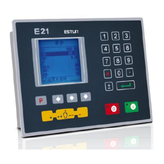
Estun E21 Installation Manual
Press brake numerical control device
Hide thumbs
Also See for E21:
- Installation manual (41 pages) ,
- Instruction book (2 pages) ,
- Operation manual (22 pages)
Table of Contents
Advertisement
Advertisement
Table of Contents

Related Manuals for Estun E21


Summary of Contents for Estun E21
- Page 1 E21 Press Brake Numerical Control Device Installation Manual V1.01 ESTUN AUTOMATION CO.,LTD Address : No.155 Jiangjun Road, Jiangning Development Zone Nanjing P.R.C 211106 Postal code:211106 TEL:025-52785569 FAX:025-52785966 WEB:www.estun.com E-mail:info@estun.com Page 1 of 38...
- Page 2 Document Revision Record Serial Version Revision Description Revised by Appr Remarks Date oved V1.00 2012-6-4 Yao Qing V1.01 2012-6-6 Update Yao Qing Assembly Drawings Page 2 of 38...
-
Page 3: Preface
Preface Target reader This manual is applicable to operators of E21 press brake machine numerical control device, including: Machine tool operators Installation and maintenance personnel Range of application Installation and maintenance personnel can install and operate this device properly by referring to this manual. - Page 4 numerical control systems of machine tools, 40 , humidity 93%~95% ℃ , 2 hours. Criteria: normal operation. Vibration impact, refer to JB-T 8832-2001 General requirements for numerical control systems of machine tools. Personnel Only authorized and properly trained person is allowed to operate this equipment.
-
Page 5: Table Of Contents
Content Preface .......................... 3 1 Specification......................7 1.1 Display ........................... 7 1.2 Internal memory ........................7 1.3 Electrical specification ......................7 1.4 Encoder specification ......................8 2 Installation ....................... 9 2.1 Annoucements before installation ..................9 2.2 Installation space and direction ....................9 2.3 Installation environment ...................... - Page 6 7.2.2 Equipment grounding design ..................33 7.3 Protective measures......................34 7.3.1 Measures to ensure electromagnetic compatibility ............. 34 7.3.2 Instructions to E21 electricmagnetic compability installation ........36 7.3.3 Install freewheeling diode on relay ................36 7.4 Demonstration of AC Asynchronism motor wiring ............. 36...
-
Page 7: Specification
Specification 1.1 Display LCD display Dimension of display window:54.38mm*54.38mm Dot matrix:160*160 Status light Green indicates running; Red indicates stop. 1.2 Internal memory Capable of storing 40 programs, each program includes 25 steps at most. 1.3 Electrical specification POWER Input voltage:DC24V±10% Rated current:1A INPUT Input voltage:DC24V±10%... -
Page 8: Encoder Specification
Encoder power Output voltage:DC12V±5% Allowable maximum output current:500mA Absolute temperature: Working temperature:0~40℃ Storage temperature:-20~55℃ 1.4 Encoder specification Power supply is DC 12V; Incremental encoder,single-ended output,with Z/C phase; Voltage-type output Page 8 of 38... -
Page 9: Installation
Therefore, before turning on the power supply, check the connection of input output grounding and power supply wire. . Grounding terminal of E21 digital control device must be grounded in correct way, with low impedance lower than 0.3Ω. -
Page 10: Installation Dimension
2.4 Installation dimension The installation method is panel-mounting. Installation dimension and drawings are shown in Figure 2-1. Figure 2-1 Panel Installation Dimension 2.5 Installation layout 2.5.1 Layout of rear panel Rear panel block diagram is shown in Figure 2-2, consisting of power port (POWER), input port (INPUT), output port (OUTPUT), encoder port (X, Y), and communication port (COMM). -
Page 11: Rear Panel Port Description
Figure 2-2 Rear panel layout 2.5.2 Rear panel port description Rear panel port description is shown in Table 2-1. Table 2-1 Rear panel port description Socket number External port name External port description POWER Input terminal of system power. 13 way. 24VDC, maximum drive capability 70mA, opto-coupler... -
Page 12: Overall Wiring Scheme
Socket number External port name External port description Incremental encoder single-ended output, with pulse frequency 100KHz. Meanwhile, port supplies Y-ENCODER power externally (as input power of encoder), rated voltage 12V, rated current 150mA, ripple voltage no higher than 100mV. RS232 For updating the system software. -
Page 13: Definition Of System Interface
Figure 2-4 Electrical wiring schemes It is recommended to use the relay which contains diode on coil, avoid high voltage damage the circuit when cutting inductive load. Shield layer of the encoder cable shall be connected to ground, which is the metal housing of the product, with low resistor. - Page 14 Table 2-1 Definition of external output terminal Terminal No. Signal Description Step change signal, DC +24V signal input, connect to upper dead point signal generally,beam return to upper dead point, +24V signal is START connected, system receive step change signal, system callout the next program and execute the program.
-
Page 15: Definition Of External Output Interface
Terminal No. Signal Description Common port of system input COM1 signal must be connected to 0V of I/O power. 2.6.3 Definition of external output interface Terminal definition is shown in Table 2-4. Definition of external output terminal Terminal No. Signal Description X――... -
Page 16: Definition Of Communication Interface
Table 2-1 Definition of encoder terminal Communication Incremental encoder terminal mode Pin No. 1, 6, 8, 9 2, 7 Signal definition GND of encoder cable can be connected to any pin among 1, 6, 8, 9; VCC of encoder cable can be connected to either 2 or 7; 2.6.5 Definition of communication interface The system has integrated RS232 serial interface, port adopts DB-9 plug (male). -
Page 17: Parameter Description Of Machine Tool
Parameter Description of Machine Tool 3.1 Enter parameter page Steps to entering parameter page are as below. Step 1 On Program Management page, click to enter Programming Constant page, as shown in Figure 3-1. On this page, program constant can be set. -
Page 18: Parameter Specification
Step 3 Select “1. System Parameter”, then click to enter system Parameter Setting page, as shown in Figure 3-3. SYS PARA 1/ 1PG X-digits: Y-digits: X-safe: 1.000 Y-safe: 1.000 Step delay: 3333 Range:0~3 Figure 3-3 System Parameter Setting page Description You can directly enter System Parameter Setting Page by input password “94343”and click on Program Constant page. - Page 19 Parameter name Default Parameter Parameter description value range Decompression 0~99999ms Interval between valid delay yield signal and unloading output when system starts. X axle teach 0~9999.999mm Input current axle position when teach enable. Y axle teach 0~9999.999mm Input current axle position when teach...
- Page 20 Parameter name Default Parameter Parameter description value range X over travel 0 or 1 0:disable 1:enable enable X over travel 0~9999.999mm Over travel distance, valid distance when positioning both sides X repeat enable 1~99999999 0:disable 1:enable X repeat time 0~9999ms Interval of back gauge reposition when...
- Page 21 Parameter name Default Parameter Parameter description value range Y stop distance 0~9999.999mm Advance stop range. Motor stops and carries out inertial motion when enter this range. allowable 0.05 0~99.999mm Position tolerance, tolerance in-place signal is output when reaching this range. Y over travel 0 or 1 0:disable 1:enable...
-
Page 22: Debugging
Debugging 4.1 Preparation before debugging Check E21 power line, ground wire, input/output signal wire and encoder plug for reliable and accurate connection. Check whether output voltage of 24V switch power is normal or not. 4.2 Debugging procedure Check power supply and ground wire before power on the system. - Page 23 Conversion distance between high and low speed:4000 Bilateral positioning enable:1 Y axle parameter setting:the method is similar to the setting of X axle parameter Step 2 X axle debugging Action debugging Press “+” to observe whether X axle moves backward. If the moving direction is opposite, then adjust phase sequence of X axle motor.
-
Page 24: Actual Processing
4.4 Actual processing When the above procedures are finished, roughly correct actual position of X and Y axle by teach function. Edit single step program to carry out actual processing, measure dimension of the processed work piece, then correct scale error by teach function. -
Page 25: Diagnosis
Diagnosis 5.1 Enter diagnosis page This system provides diagnosis tests for input, output, keyboard, FRAM, encoder and LCD, etc. Caution When diagnosis is in progress, please make sure oil pump is not started. Steps to enter diagnosis page are as follows: Step 1 Power on, system stays on single-step programming page, Stop Indicator is on. -
Page 26: Output Diagnosis
Figure 5-2 Input diagnosis page 5.3 Output diagnosis On “System diagnosis” interface, select “2. Output diagnosis” to enter diagnosis interface, as shown in Figure 5-3. OUT01-13 on interface is output corresponding to 1-13 way. Use cursor key to select output terminal, press , the selected output terminal is open and on. -
Page 27: Fram Diagnosis
Figure 5-4 Keyboard diagnosis page 5.5 FRAM diagnosis On “System diagnosis” interface, select “4.FRAM diagnosis” to enter storage diagnosis interface, as shown in Figure 5-5. Click to enter storage diagnosis, as shown in Figure 5-6. Figure 5-5 Storage diagnosis page Figure 5-6 Storage diagnosing page Page 27 of 38... -
Page 28: Encoder Diagnosis
5.6 Encoder diagnosis On “System diagnosis” interface, select “5.Enc. Diagnosis” to enter encoder diagnosis interface, as shown in Figure 5-7. Rotate encoder, the page will display corresponding pulse change. C pulse signal will jump between 0 and ENC. DIAG. Encoder1: Encoder1 C:... -
Page 29: Maintenance
Maintenance 6.1 Instructions to maintenance In order to use this system safely and properly, follow the instructions. Caution When power is on or system operates normally, do not open cover plate or panel as it may damage the components. Wiring and inspection shall be done by professionals. -
Page 30: Periodic Inspection
Table 6-1 Routine inspection Inspection item Standard Standard Treatment content specification Basic Check installed Fasten installation screw properly. screw. status loosening, and system check seal for drop. port Check IO port Correct wiring. Correct connection connection for wiring. status loosening Connection Check terminal Screw... - Page 31 Inspection item Standard Standard Treatment content specification Install Tension, Mobile Module must Secure mobility module installed screw. securely. I/O module looses, fasten them by screws. Dust and Visual No dust or Remove and foreign observation foreign matter clean. matter is allowed. attachmen Connecti Tightness...
-
Page 32: Appendix
7.2 Grounding design 7.2.1 Ground classification in equipment cabinet Ground in equipment cabinet is divided into three categories: Signal ground: for example, signal reference in E21 controller; Shield ground: the shield layer of communication cable can prevent the system ... -
Page 33: Equipment Grounding Design
RC net. RC network of E21 is integrated inside the product with one end connect to signal ground, and the other end connect to ground (three pins of POWER terminal), as shown in Figure 7-1. -
Page 34: Protective Measures
7.3 Protective measures 7.3.1 Measures to ensure electromagnetic compatibility E21 and its components are specially designed for industrial environment with strong electromagnetic compatibility. But when install and operate, take possible interference by the outside into account, and improve reliability and stability of the system. - Page 35 Table 7-1 Ways to interfere coupling Coupling mode Cause Typical cases Direct electric Two or more circuits Many equipment share one power coupling use one guide line supply; Electrostatic discharge, etc. Capacity Capacity coupling When cables are laid in parallel, coupling will generate...
-
Page 36: Instructions To E21 Electricmagnetic Compability Installation
7.3.2 Instructions to E21 electricmagnetic compability installation E21 may be installed outside the cabinet. If work environment is poor, keep E21 close to cabinet as much as possible; Metal housing shall connect to protective ground via earth conductor, and ground resistance shall be no higher than 0.3 ohm;... - Page 37 Page 37 of 38...
- Page 38 Page 38 of 38...
Need help?
Do you have a question about the E21 and is the answer not in the manual?
Questions and answers