Table of Contents
Advertisement
Quick Links
Advertisement
Table of Contents

Related Manuals for Estun Trio MC404-Z


Summary of Contents for Estun Trio MC404-Z
- Page 1 MC404-Z 4 AXIS MOTION COORDINATOR USER MANUAL...
- Page 2 MC404-Z About this Manual Purpose This manual provides the information required for the Selection, Wiring, Connection, Setup, Operation and Functions of the MC404-Z Motion Coordinator. Please read and understand this manual to ensure correct usage of the product. Terms Terms that may be used in this manual are defined as follows. Term Meaning Axis...
-
Page 3: Revision History
MC404-Z Revision History Date Version Revised Contents 10 Nov 2020 1.00 Draft 12 Nov 2020 1.01 Update 1 – minor edits 27 Nov 2020 1.02 Update 2 – added EMC section and panel mount dimensions 22 Dec 2020 1.03 Updated product comparison table 28 May 2021 1.04 Added AOUT and absolute encoder information to specifications... - Page 4 MC404-Z All goods supplied by Trio are subject to Trio’s standard terms and conditions of sale. This manual applies to systems based on the Motion Coordinator MC404-Z. The material in this manual is subject to change without notice. Despite every effort, in a manual of this scope errors and omissions may occur.
- Page 5 MC404-Z Safety Warning During the installation or use of a control system, users of Trio products must ensure there is no possibility of injury to any person, or damage to machinery. Control systems, especially during installation, can malfunction or behave unexpectedly. Users must ensure that in all cases of normal operation, controller malfunction, or unexpected behaviour, the safety of operators, programmers or any other person is totally ensured.
-
Page 6: Table Of Contents
MC404-Z Contents Revision History .................... 2 User Manual MC404-Z ..................7 Overview ....................7 Programming ..................... 7 I/O Capability .................... 7 Communications ..................8 IP Address reset ..................8 Removable storage ..................8 Axis positioning functions ................8 LED indicators ................... 9 Connections to the MC404-Z ................ - Page 7 MC404-Z Electromagnetic Compatibility ..............24 Intended conditions of use ................ 24 EMC Considerations ................24 Product specific requirements ..............24 Recommended Installation ................ 26 Surge Protection ..................26 Surge protection device ................27 Cable Shields ..................28 Document Version: 1.05 ©...
-
Page 8: User Manual Mc404-Z
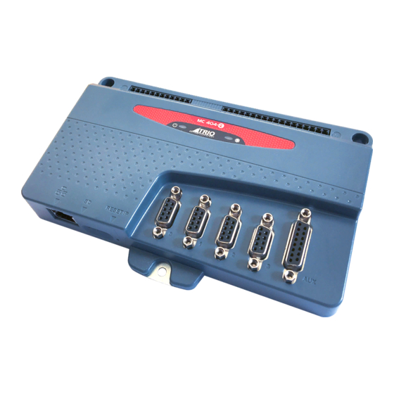
MC404-Z User Manual MC404-Z Overview The Motion Coordinator MC404-Z is based on Trio’s high-performance ARM Cortex-M7 double-precision technology and provides 4 axes of pulse+direction or quadrature output control for stepper drives or pulse-input servo drives. Trio uses advanced FPGA techniques to reduce the size and fit the pulse output and servo circuitry in a compact panel mounted package. -
Page 9: Communications
MC404-Z be defined to be used by the controller for end of travel limits, registration, datuming and feedhold functions if required. The MC404-Z can have up to 512 external Input and Output channels connected using DIN rail mounted CAN I/O modules. These units connect to the built-in CANbus port. -
Page 10: Led Indicators
MC404-Z Consecutive movements may be merged to produce continuous path motion and the user may program the motion using programmable units of measurement (e.g. mm, inches, revs etc.). The module may also be programmed to control only the axis speed. The positioner checks the status of end of travel limit switches which can be used to cancel moves in progress and alter program execution. -
Page 11: Amplifier Enable (Watchdog) Relay Output
MC404-Z Amplifier enable (Watchdog) relay output An internal solid-state relay contact is available to enable external drives when the controller has powered up correctly and the system and application software are ready. The amplifier enable relay has an ON resistance of 25Ω at 100mA. The enable relay will be open circuit if there is no power on the controller OR a motion error exists on an axis OR the user program sets it open with the WDOG = OFF command. - Page 12 MC404-Z Axes 0, 1 and 2 RS422 line driver output for Step, Direction and Enable signals or alternatively can be set for A, B and Enable. Pin # Description Step + / A + Step - / A - Direction + / B + Direction - / B - Enable + Enable -...
-
Page 13: Registration
MC404-Z Registration MC404-Z encoder port has 2 available registration events. These are assigned in a flexible way to any of the first 8 digital inputs or can be used with the Z mark input on the encoder port. I/O connector 1 This connector is used both to provide the 24 Volt power to the MC404-Z and provide power and connections for the 24V NPN outputs. -
Page 14: Auxiliary Connector
MC404-Z Inputs 0 to 7 can be used as registration inputs allocated by REG_INPUTS for axis 3, using the REGIST command. Auxiliary connector The 15 way D-Type connector is a multi-function socket that has 1 x RS232 port, 1 x RS422/RS485 port, 1 x CANbus port, Anlogue I/O and connections for the WDOG solid-state relay. -
Page 15: Connection Example 1
MC404-Z Connection example 1 Stepper drives. All outputs are RS422 differential line drivers rated at 5V 10mA. The 0V may be omitted if the stepper drive inputs are fully opt0-isolated. Connection example 2 Servo drives with 24V enable Many Servo drives that have pulse and direction inputs for motion also use a 24V enable input. -
Page 16: Software
MC404-Z The WDOG signal may be connected to multiple drive enable inputs. WDOG-A and WDOG-B are a volt-free solid- state relay. They may be used with +24V on either terminal. Software Motion Perfect version 5 or later is required for configuring, programming and system debug. A PC running Microsoft Windows (Windows 10 or later recommended) is required. -
Page 17: Motion Perfect Version 5
MC404-Z Click Properties and select Use the following IP address. Set an IP address in the same subnet as the MC404-Z. Usually this will be 192.168.0.xxx. Click OK and close the Ethernet setup dialogues. Motion Perfect version 5 Launch Motion Perfect and select the IP address of the MC404-Z. By default this will be 192.168.0.250. - Page 18 MC404-Z If the IP Address of the MC404-Z is not known, then reset it by holding the IP Reset button located next to the SD card slot while powering up the MC404-Z. This will reset the IP_ADDRESS to 192.168.0.250. Motion Perfect in Synchronised connection mode. The MC404-Z is capable of running up to 16 axes total including virtual axes, of which 4 are real axes.
-
Page 19: Firmware
MC404-Z Firmware The MC404-Z comes pre-installed with the firmware version which was released to production at the time of manufacture. Newer versions may be available to download from the Trio website and it is recommended to check if an update is available before using the Motion Coordinator for an application. -
Page 20: Mounting
MC404-Z Mounting 2 x upper slots 4.2 mm width. 1 x lower mounting hole 4.4 mm dia. Ventilation: When the MC404-Z is mounted in an enclosed cabinet, there must be an adequate volume of circulating air to maintain the environmental temperature within the operating temperature range. - Page 21 MC404-Z Control Inputs Forward Limit (user selectable) Reverse Limit Datum Input Feedhold Input Communication Ports RS232 channel: up to 128k baud. RS485 channel: up to 128k baud CANbus port (CANopen option) Ethernet: 10/100 BaseT multiple port connection. Position Resolution 64 bit position count Speed Resolution 32 bits.
-
Page 22: Product Comparison Table
MC404-Z Amplifier Enable Output Normally open solid-state relay rated 24V ac/dc nominal Maximum load 100mA Maximum Voltage 29V Analogue Inputs 1 x 12 bit 0 .. 10V Analogue Outputs 1 x 10 bit 0 .. 10V. Response time 30 msec to 90% of value. Step+direction output RS422 differential line driver Max frequency 2MHz... - Page 23 MC404-Z Axis 4 +/- 10V out + Encoder Reference Encoder Input MC403-Z MC403 MC405 MC404-Z Axis 0 (Inc. / SSI / Endat / BiSS) I/S/E/B I/S/E/B Axis 1 (Inc. / SSI / Endat / BiSS) I/S/E/B I/S/E/B Axis 2 (Inc. / SSI / Endat / BiSS) I/S/E/B I/S/E/B Axis 3 (Inc.
- Page 24 MC404-Z VR memory 4096 4096 4096 4096 TABLE memory 512000 512000 512000 512000 User (program) memory check check check 3 MB Document Version: 1.05 © 2021 All rights reserved.
-
Page 25: Electromagnetic Compatibility
MC404-Z Electromagnetic Compatibility Trio Motion Technology products are certified to comply with the requirements of Annex I to the Directive 2014/30/EU on Electromagnetic disturbance and Electromagnetic immunity. To achieve this compliance, certain requirements or best engineering practices must be implemented by the corresponding system designer. Intended conditions of use Trio Motion Technology products are designed for operation in Industrial environments with high noise levels that may induce currents or electrical potentials that are damaging to... - Page 26 MC404-Z Feature Requirements Notes 0V wire (current return) 1. Always connect ALL 0V current return wires MC404-Z stepper 0V, encoder 0V and Auxiliary connector 0V 2. Do not use the screen for 0V current return are all common together. 3. It is highly recommended to avoid connecting 24V supply 0V is isolated.
-
Page 27: Recommended Installation
MC404-Z Serial ports 2. Connect screen to Chassis at both ends. connector shell. 3. 0V reference connected at both ends. 0V on Aux connector, pins 4, 8 and 12 are common 0V. Ethernet 1. TIA Cat5e, minimum. Overall Foil Braided Shield with Unshielded Twisted Pairs. -
Page 28: Surge Protection Device
MC404-Z Distributed power supply If the device is connected to a distributed power supply or the cable length between the power source and the device is longer than 3 metres, then a surge protection device must be fitted to comply with the CE EMC directive. Distributed power supply with surge protection Surge protection device Protection device - Minimum specification... -
Page 29: Cable Shields
MC404-Z Cable Shields Both ends of the encoder cable’s screen must be connected using a 360 degree contact and not a pig-tail connection. The 0V must be connected separately from the screen. Make sure that encoder cables are specified with one extra wire to carry the 0V. All serial cables must be terminated in the 15-pin auxiliary connector.
Need help?
Do you have a question about the Trio MC404-Z and is the answer not in the manual?
Questions and answers