Sign In
Upload
Manuals
Brands
Estun Manuals
Robotics
ERC3-C1 Series
Estun ERC3-C1 Series Manuals
Manuals and User Guides for Estun ERC3-C1 Series. We have
3
Estun ERC3-C1 Series manuals available for free PDF download: Operating Instructions Manual, Operation Manual, Operation Instructions Manual
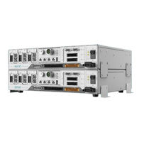
Estun ERC3-C1 Series Operating Instructions Manual (105 pages)
Robot Control Cabinet
Brand:
Estun
| Category:
Controller
| Size: 5 MB
Table of Contents
Foreword
4
Revision History
5
Definition of Users
6
Safety Precautions
6
Safety Symbols
6
Safety Precautions
7
Precautions for Maintenance
9
Other Safety Precautions
10
Warning and Caution Signs
10
Security Category
11
Way to Stop Robots
11
Contents
18
Table of Contents
18
Chapter 1 Product Information
21
Information on Nameplate
21
Designation
22
Product Dimensions
22
Components
23
External Interface
23
Technical Parameters
24
Chapter 2 Transportation & Installation
26
Handling Procedures
26
Installation Requirements
26
Installation Methods
27
Horizontal Installation
27
Vertical Installation
28
Stacking Installation
30
Chapter 3 Wiring
33
Wiring Precautions
33
Selection of Circuit Breaker/Air Switch
34
Power Cable Selection
35
External Interface Description
35
Connection Diagram
37
Power Supply Wiring
37
LED Explanation
38
Power Wiring
39
Power Line Interface Explanation
39
Power Line Wiring
44
Encoder Wiring
45
Connection Diagram
45
Encoder Interface Explanation
45
Teach pendant Wiring
46
Precautions for Using Teach pendant
46
Teach pendant Interface Description
47
Teach pendant Specifications
48
Appearance of Teach pendant
48
IO Wiring
49
DI Wiring
50
DO Wiring
54
Communication Connection
57
Communication Signal Description
57
Recommended Communication Cables
57
USB Interface
58
Ethercat Wiring
58
Safety Io
58
SAFETY Interface Description
60
Start Confirmation Wiring Method
61
External E-Stop Wiring Method
62
Limit Switch Wiring Method
63
Safety Door Wiring Method
64
Auto Protection Stop Wiring Method
65
E-Stop Output Wiring Method
67
Chapter 4 (Optional) Expansion Cards
68
Expansion Slot Description
68
Installing Steps
69
DI Expansion Card
71
Expansion Card Information
71
Installation Dimensions
71
Terminal Definitions
71
Port Specifications
72
External Wiring Diagram
72
DO Expansion Card
74
DO Expansion Card Description
74
DO Expansion Card Information
74
Installation Dimensions
74
Definition of NPN Type Digital Output Expansion Card Terminal
74
Definitions of PNP Type Digital Output Expansion Card Terminals
76
ABZ Expansion Card
78
Expansion Card Information
78
Installation Dimensions
78
Terminal Definitions
79
Wiring Method
80
Ethernet Port Adapter Expansion Card
80
Expansion Card Information
80
Installation Dimensions
81
Terminal Definitions
81
Recommended Communication Cables
81
Wiring Method
82
Chapter 5 Servo Parameter Settings
83
Check before Power-On
83
Pn Parameter Settings for Teach pendant
83
Introduction to Servo Parameters
85
Instructions for Use
85
Detailed Explanation of Parameters
85
Chapter 6 View Servo Alarms and Handling
92
View Alarms Using Teach pendant
92
Log
93
Help
93
Alarm List
95
Chapter 7 Maintenance
102
Maintenance Precautions
102
Daily Inspection
102
Regular Inspection
103
Program Backup and Loading
104
Program Backup
104
Program Loading
105
List of Spare Parts
105
Advertisement
Estun ERC3-C1 Series Operation Manual (99 pages)
Control Cabinet
Brand:
Estun
| Category:
Robotics
| Size: 5 MB
Table of Contents
Foreword
4
Revision History
5
Definition of Users
6
Safety Precautions
6
Safety Symbols
6
Safety Precautions
7
Warning and Caution Signs
10
Way to Stop Robots
11
Contents
12
Table of Contents
12
Chapter 1 Product Information
15
Information on Nameplate
15
Designation
16
Product Dimensions
16
Components
17
Technical Parameters
18
Chapter 2 Transportation & Installation
20
Handling Procedures
20
Installation Requirements
20
Installation Methods
21
Horizontal Installation
21
Vertical Installation
22
Stacking Installation
24
Chapter 3 Wiring
27
Wiring Precautions
27
Selection of Circuit Breaker/Air Switch
28
Power Cable Selection
29
External Interface Description
29
Connection Diagram
31
Power Supply Wiring
31
LED Explanation
32
Power Wiring
33
Power Line Interface Explanation
33
Power Line Wiring
38
Encoder Wiring
38
Connection Diagram
39
Encoder Interface Explanation
39
Teach pendant Wiring
40
Precautions for Using Teach pendant
40
Teach pendant Interface Description
41
Teach pendant Specifications
42
Appearance of Teach pendant
42
IO Wiring
43
DI Wiring
44
DO Wiring
48
Communication Connection
51
Communication Signal Description
51
Recommended Communication Cables
51
USB Interface
52
Ethercat Wiring
52
Safety Io
52
SAFETY Interface Description
54
Start Confirmation Wiring Method
55
External E-Stop Wiring Method
56
Limit Switch Wiring Method
57
Safety Door Wiring Method
57
Auto Protection Stop Wiring Method
59
E-Stop Output Wiring Method
60
Chapter 4 (Optional) Expansion Cards
61
Expansion Slot Description
61
Installing Steps
62
DI Expansion Card
64
Expansion Card Information
64
Installation Dimensions
65
Terminal Definitions
65
Port Specifications
66
External Wiring Diagram
66
DO Expansion Card
67
DO Expansion Card Description
67
DO Expansion Card Information
67
Installation Dimensions
68
Definition of NPN Type Digital Output Expansion Card Terminal
68
Definitions of PNP Type Digital Output Expansion Card Terminals
70
ABZ Expansion Card
72
Expansion Card Information
72
Installation Dimensions
72
Terminal Definitions
73
Wiring Method
74
Ethernet Port Adapter Expansion Card
74
Expansion Card Information
74
Installation Dimensions
74
Terminal Definitions
75
Recommended Communication Cables
75
Wiring Method
75
Chapter 5 Servo Parameter Settings
77
Check before Power-On
77
Pn Parameter Settings for Teach pendant
77
Introduction to Servo Parameters
79
Instructions for Use
79
Detailed Explanation of Parameters
79
Chapter 6 View Servo Alarms and Handling
86
View Alarms Using Teach pendant
86
Log
87
Help
87
Alarm List
89
Chapter 7 Maintenance
96
Maintenance Precautions
96
Daily Inspection
96
Regular Inspection
97
Program Backup and Loading
98
Program Backup
98
Program Loading
98
List of Spare Parts
99
Estun ERC3-C1 Series Operation Instructions Manual (49 pages)
Robot Body
Brand:
Estun
| Category:
Robotics
| Size: 2 MB
Table of Contents
Instructions for Safe Use
4
Safety Symbols
4
Precautions for Operation
5
Preface
9
Table of Contents
10
Contents
11
Product Specifications
12
Designation
12
Components and Outline Dimensions
13
Specifications
15
Environment and Installation
16
Environment
16
Special Environmental Conditions
16
Stand
17
Installing Dimensions of Robot
18
Handling
20
Installation
22
Grounding Guidelines
23
Cable Connection
24
User Wiring and Piping
25
Wiring (Cables)
25
Air Tube
25
Relocation and Storage
26
Precautions
26
Relocation
27
Fixture End Setting
29
Mounting Fixture End
29
Shaft
29
Layout
29
Installation of Camera/Pneumatic Valve, Etc
29
Equivalent Weight Calculation
30
Motion Space
32
Maintenance
33
Maintenance Inspection
33
Inspection When Power Is off (no Motion)
33
Inspection When Power Is on (During Operation)
34
Robot Lubrication
34
Steps to Replace Reducer Grease
36
Steps to Release Residual Pressure in the Grease Chamber
36
Lubrication of Ball Screw Splines
37
Tightening of Hexagon Socket Bolts
37
Maintenance of Timing Belts
38
Signs of Timing Belt Failure
39
Maintenance of Timing Belts
39
Inspection of Oil Seepage
40
Zero Calibration
41
Introduction
41
Calibration with Instrumentation
41
Mechanical Zero Calibration
42
Troubleshooting
44
Required Tools
44
Replacement of Servo Motor Components
46
Appendix
47
Appendix A List of Recommended Spare Parts for ER20C
47
Revision Record
48
Advertisement
Advertisement
Related Products
Estun ERC-C2-E4SA
Estun ERC-C2-E4SC
Estun ERC3-C1-X1A4
Estun ERC3-C1-X1B4
Estun ERC3-C1-X1C4
Estun ERC3-C1-X1B6
Estun ERC3-C1-X1C6
Estun ERC-S3 L Series
Estun ER8-2000-CW
Estun ER220B-2650
Estun Categories
Robotics
Controller
Servo Drives
Control Systems
Monitor
More Estun Manuals
Login
Sign In
OR
Sign in with Facebook
Sign in with Google
Upload manual
Upload from disk
Upload from URL