Advertisement
Quick Links
Advertisement

Subscribe to Our Youtube Channel
Related Manuals for Estun TRIO Flex-7


Summary of Contents for Estun TRIO Flex-7
- Page 1 Flex-7 EtherCAT 128 AXIS MOTION COORDINATOR...
- Page 2 Flex-7 About this Manual Purpose This manual provides the information required for the Selection, Wiring, Connection, Setup, Operation and Functions of the Flex-7 Motion Coordinator. Please read and understand this manual to ensure correct usage of the product. Terms Terms that may be used in this manual are defined as follows. Term Meaning Axis...
- Page 3 Flex-7 Revision History Date Version Revised Contents 09/08/24 0.01 Initial draft Document Version: 1.00 © 2024 All rights reserved.
- Page 4 Flex-7 All goods supplied by Trio are subject to Trio’s standard terms and conditions of sale. This manual applies to systems based on the Motion Coordinator Flex-7. The material in this manual is subject to change without notice. Despite every effort, in a manual of this scope errors and omissions may occur.
- Page 5 Flex-7 Safety Warning During the installation or use of a control system, users of Trio products must ensure there is no possibility of injury to any person, or damage to machinery. Control systems, especially during installation, can malfunction or behave unexpectedly. Users must ensure that in all cases of normal operation, controller malfunction, or unexpected behaviour, the safety of operators, programmers or any other person is totally ensured.
- Page 6 Flex-7 Contents Revision History .................... 2 User Manual Flex-7 ..................7 Overview ....................7 Programming ..................... 7 I/O Capability .................... 8 Communications ..................9 IP Address reset ............. Error! Bookmark not defined. Removable storage ..................9 Axis positioning functions ................9 LED indicators ...................
- Page 7 Flex-7 Surge Protection ..................25 Surge protection device ................26 Cable Shields ..................27 Document Version: 1.00 © 2024 All rights reserved.
- Page 8 Flex-7 User Manual Flex-7 Overview The Motion Coordinator Flex-7 is based on Trio’s high- performance ARM Cortex-A53 double-precision technology and provides up to 128 axes of coordinated motion using the EtherCAT bus system to connect to Drives and I/O. Benefiting from a re-architected communications interface and a quad core processor the Flex-7 offers a step change in performance in Trio’s Flexible Machine Controller range.
- Page 9 Flex-7 Display The Flex-7 display features a number of display modes.. The modes can be accessed by pressing the toggle button. After 1 minute of idle time, the display will revert to screensaver mode (scrolling logo). Pressing the screen toggle button will return the display to the last display mode. Short Press Long Press Ethernet Information...
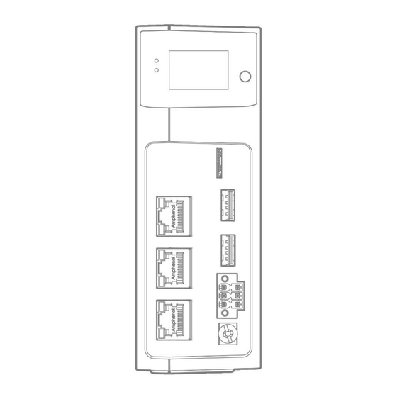
- Page 10 Flex-7 Communications Two 100 base-T Ethernet ports are fitted as standard and this is the primary communications connection to the Flex-7. Protocols supported include Telnet (Client and Server), Modbus TCP (Client and Server), Ethernet IP (Slave), Profinet (Slave) and the TrioPCMotion DLL/ActiveX channel.
- Page 11 Flex-7 Connections to the Flex-7 24V power supply and CAN connector The Flex-7 requires a Class 2 transformer or power source within the range 18..29V d.c. Current consumption is 350mA when a full set of 16 Flexslice I/O modules are connected to the EBUS connector. A 3 part connector is provided which has push-fit cable entry ports with spring clamp and positive push to release operation.
- Page 12 Flex-7 Straight through (patch) or cross-over cables can be used between EtherCAT devices. Minimum cable specification: CAT 5e shielded SF/UTP cable is recommended. USB port connection (x2) The USB sockets can be used with a USB thumb drive to provide external data storage. These can be written to and read from using the file access channels (#40-#48) in TrioBASIC.
- Page 13 Flex-7 All Flexslice modules support automatic addressing with the master able to automatically detect and configure the modules on startup. The Flex-7 supports up to 16 input/output modules which have a positive mechanical lock and bus connector, making a reliable “back-bone” style connection (EBUS). The complete assembly can be DIN rail mounted.
- Page 14 Flex-7 EBUS load calculator The table above shows the load weighting for a range of Flexslice modules. Multiply Unit Load by the quantity of modules of that type. The sum of all modules thus weighted must not exceed 16. The EBUS load calculator may be downloaded from Trio’s website. Support Software Motion Perfect version 5 or later is required for configuration, programming and system debug.
- Page 15 Flex-7 Click Properties and select Use the following IP address. Set an IP address in the same subnet as the Flex-7. Usually this will be 192.168.0.xxx. Click OK and close the Ethernet setup dialogues. Document Version: 1.00 © 2024 All rights reserved.
- Page 16 Flex-7 Motion Perfect version 5 Launch Motion Perfect and select the IP address of the Flex-7. By default this will be 192.168.0.250. Click the Apply and Connect button. If the IP Address of the Flex-7 is not known, it can be found by cycling though the Flex-7 display screen.
- Page 17 Flex-7 Motion Perfect in Synchronised connection mode. Software functions The Flex-7 contains a stand-alone operating system which includes a rich set of built-in motion functions accessible from both the interpreted Motion iX text language and the IEC- 61131-3 standard PLC language. A short summary of the main functions is shown in the table below.
- Page 18 Flex-7 CAMBOX User defined constantly changing ratio between the axis and its driving axis. (Cam shape supplied by user program) MOVEPICK Pre-defined pick and place profile. User defined overlap and withdraw distances. EtherCAT network EtherCAT slave devices may be added to make a network. Device addresses will default to their position on the network with the local I/O being located first ahead of any external devices.
- Page 19 Flex-7 Example 2 Example 3 Document Version: 1.00 © 2024 All rights reserved.
- Page 20 Flex-7 Adding axes Depending on the feature codes applied to the unit, the Flex-7 will be able to connect and start a certain number of axes (drives). It is possible to extend the number of axes by purchasing a Feature Enable Code (FEC) from the original supplier of the Flex-7.
- Page 21 Flex-7 Dimensions Mounting The Flex-7 has a standard DIN rail mount with over-centre clip operated by a lever on the lower face. It must be installed on an unpainted metal plate with DIN rail which is connected to earth. Ventilation: When the Flex-7 is mounted in an enclosed cabinet, there must be an adequate volume of circulating air to maintain the environmental temperature within the operating temperature range.
- Page 22 Flex-7 Specifications Specification table Size 147 mm x 107 mm x 51 mm (HxWxD) Weight 160g Operating Temp. 0 - 45 degrees C EMC (CE) EMISSIONS – EN IEC 61000-6-4 : 2019 IMMUNITY – EN IEC 61000-6-2 : 2019 EMC (UKCA) EMISSIONS –...
- Page 23 Flex-7 12 Mbyte user program memory Automatic flash EPROM program and data storage 65536 global VR data in FLASH memory (automatic-store) TABLE 512000 x 64 bit TABLE memory Real Time Clock Super-capacitor support for 10 days of power off SD Card Standard micro-SD Card FAT 32, up to 32 GB Stores programs and data Can be used for firmware update, user program installation...
- Page 24 Flex-7 Electromagnetic Compatibility Trio Motion Technology products are certified to comply with the requirements of Annex I to the Directive 2014/30/EU on Electromagnetic disturbance and Electromagnetic immunity. To achieve this compliance, certain requirements or best engineering practices must be implemented by the corresponding system designer. Intended conditions of use Trio Motion Technology products are designed for operation in Industrial environments with high noise levels that may induce currents or electrical potentials that are damaging to...
- Page 25 Flex-7 Feature Requirements Notes 0V wire (current return) 1. Always connect ALL 0V current return wires Flex-7 stepper 0V, encoder 0V and Auxiliary connector 0V are 2. Do not use the screen for 0V current return all common together. 3. It is highly recommended to avoid connecting 24V supply 0V is isolated.
- Page 26 Flex-7 Serial ports 2. Connect screen to Chassis at both ends. connector shell. 3. 0V reference connected at both ends. 0V on Aux connector, pins 4, 8 and 12 are common 0V. Ethernet 1. TIA Cat5e, minimum. Overall Foil Braided Shield with Unshielded Twisted Pairs.
- Page 27 Flex-7 Distributed power supply If the device is connected to a distributed power supply or the cable length between the power source and the device is longer than 3 metres, then a surge protection device must be fitted to comply with the CE EMC directive. Distributed power supply with surge protection Surge protection device Protection device - Minimum specification...
- Page 28 Flex-7 Cable Shields Both ends of the encoder cable’s screen must be connected using a 360 degree contact and not a pig-tail connection. The 0V must be connected separately from the screen. Make sure that encoder cables are specified with one extra wire to carry the 0V. All serial cables must be terminated in the 15-pin auxiliary connector.
Need help?
Do you have a question about the TRIO Flex-7 and is the answer not in the manual?
Questions and answers