Advertisement
Quick Links
INSTALLATION, OPERATION & APPLICATION GUIDE
For more information on our complete range of American-made products – plus wiring
diagrams, troubleshooting tips and more, visit us at www.icmcontrols.com
FEATURES
• Controls the function of an ECM (electronically commutated) motor,
gas valve, ignitor, and flame sensor.
• Continuously monitors all system safetys including high temperature
limit, pressure switch and auxiliary rollout switch.
• Detects and communicates faults using diagnostic LEDs to aid
troubleshooting.
• Employs timed safety lockouts when necessary.
REPLACES
• Nordyne: 1021575R
SPECIFICATIONS
Input:
• Line Voltage: 120VAC
• Control Voltage: 18-30VAC
• Frequency: 60Hz and 50Hz
• Fuse Rating: 3 A
Output:
• ECM Output Relay:
- Heat N.O. – 1A max @ 24 VAC
- Cool N.C. – 1A max @ 24 VAC
• Inducer – 1/100 HP (0.69A) @ 120VAC
• HSI – 6.0A Resistive @ 120 VAC
• Gas valve – 0.5A @ 24 VAC
Environmental:
• Operating Temperature: -40° to 80°C
• Storage Temperature: -40° to 85°C
• Humidity: 5% - 95% R.H. (non-condensing) at +55°C
• Flame spread: UL # MH 15387 VOL. 1, SEC.10
Dimensions:
• Dimensions: 5.75" L x 4.3" W x 0.50" D
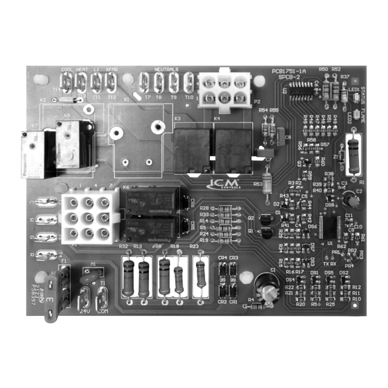
Furnace Control Board with an ECM Blower Output
INTRODUCTION
The ICM2820 furnace control board will control the functions of the
furnace including the induced draft blower, circulator blower, gas
valve, ignitor, and flame sensor based on inputs from a thermostat and
various sensors in the furnace. The ICM2820 control will also detect
faults and communicate the faults while in service and display the
faults through its on-board LED as well as employ a timed safety lock-
out when the conditions warrant.
OPERATIONAL SEQUENCE
The thermostat calls for heat by energizing the "W" terminal. The control
energizes the induced draft motor and waits for the pressure switch to
close and runs the inducer for a 45 second prepurge time.
After the inducer pre-purge, the control energizes the Hot Surface
Ignitor. After the Hot Surface Ignitor warm up period, the control
energizes the main gas valve. Once the burner lights, flame must be
proven by the flame sensor and the Hot Surface Ignitor turns off. Once
the flame is proven, the control begins a 30 second On-delay then
energizes the main blower at the HEAT speed.
When the thermostat demand for heat is satisfied, the control de-
energizes the gas valves. The inducer output remains on for a 30 second
post-purge period. The indoor blower motor is de-energized after a 120
second blower off delay.
ELECTROSTATIC DISCHARGE (ESD) PRECAUTIONS
Use caution when installing and servicing the furnace board to avoid
and control electrostatic discharge, which can negatively impact
electronic components. Following the precautions will protect the
control from ESD by safely discharging static electricity buildup to
ground.
1. Disconnect all power to the furnace. Do not touch the control or the
wiring prior to discharging your body's electrostatic charge to ground.
2. To ground yourself, touch your hand and tools to a clean, metal
(unpainted) surface near the control board.
3. Touch the chassis before servicing the furnace. Your body recharges
with static electricity as you shuffle your feet or move around, and you
must reground yourself.
4. Reground yourself if you touch ungrounded items.
5. Reground yourself before handling a new control. Store used and new
controls in separate containers before touching ungrounded objects.
6. ESD damage can also be prevented by using an ESD service kit.
ICM2820
Advertisement

Related Manuals for ICM Controls ICM2820


Summary of Contents for ICM Controls ICM2820
- Page 1 INTRODUCTION The ICM2820 furnace control board will control the functions of the furnace including the induced draft blower, circulator blower, gas valve, ignitor, and flame sensor based on inputs from a thermostat and various sensors in the furnace.
- Page 2 REMOVING EXISTING CONTROL INSTALLING NEW CONTROL To service control, and prior to CAUTION 1. GROUND YOURSELF. When handling the circuit board, hold it by the disconnection, label all wires. Failure to edges. do so may result in wiring errors which can cause dangerous 2.
- Page 3 LED FAULT CODES FAULT CODE (# BLINKS) FAULT CONDITION TROUBLESHOOTING Red LED Control OK in standby, heat Steady ON or fan modes Check proper input voltage and fuse; if unresolved, replace control. Check for Steady OFF Mis-wired gas valve shorted or mis-wired gas valve, check pressure switch for proper operation. Or Check for defective gas valve.
- Page 4 WIRING DIAGRAM MOTOR 120 VAC 24 VAC 120 VAC EARTH CHASSIS COOL NEUTRALS HEAT XFMR ICM2820 P1 PINOUT K6 K5 FLAME SENSE P2 PINOUT LIMITS PIN CONNECTIONS 1 – NC LEGEND 2 – 24 VAC Comm Aux – Auxiliary Limit Switch 3 –...
Need help?
Do you have a question about the ICM2820 and is the answer not in the manual?
Questions and answers