Table of Contents
Advertisement
Quick Links
FEATURES & SPECIFICATIONS
FEATURES
• Controls the gas valve, inducer draft
motor, circulating blower and hot
surface ignitor
• Monitors system pressure and limit
switches
• Microprocessor based precision
• Twinning compatible with another
ICM2810 control board
• Diagnostic LEDs aid in testing and
troubleshooting
• Replaces: Goodman PCBBF136 and
PCBBF140
SAFETY CONSIDERATIONS
CAUTION! Only trained personnel should install or service heating equipment. When working with heating equipment, be sure to read and
understand all precautions in the documentation, on labels, and on tags that accompany the equipment. Failure to follow all safety
guidelines may result in damage to equipment, severe personal injury or death.
ELECTROSTATIC DISCHARGE (ESD) PRECAUTIONS
Use caution when installing and servicing the furnace to avoid and control electrostatic discharge. ESD can impact electronic components. These
precautions must be followed to prevent ESD from hand tools and personnel. Following these precautions will protect the control from ESD by
discharging static electricity buildup to ground.
1. Disconnect all power to the furnace. Do not touch the control or the wiring prior to
discharging your body's electrostatic discharge to ground.
2. To ground yourself, touch your hand and tools to a clean, metal (unpainted) furnace
surface near the control board.
3. Service the furnace after touching the chassis. Your body will recharge with static
electricity as you shuffle your feet or move around, and you must reground yourself.
INSTALLATION
Remove Existing Control:
1. Turn thermostat to OFF position or set it to the lowest possible setting.
2. Turn OFF electrical supply to furnace.
CAUTION! Failure to turn off gas and electric supplies can result in
explosion, fire, death, or personal injury.
Install New Control:
1. Ground yourself properly before installing the new ICM2810 control board.
2. Mount the new control using any screws and fasteners previously removed.
Main Operation:
On the application of power, the control will continuously monitor the rollout switch, limit switch, pressure switch, gas valve output and flame sense. During a Call
for Heat, the control makes sure the limit switch is closed and the pressure switch contact is open before turning on the Inducer blower, which will be energized for
15-seconds in a pre-purge mode. Following the pre-purge period, the pressure switch contact is closed and power is applied to the hot surface ignitor (there is a
18-second warm-up period). The gas valve is energized if a flame is sensed during this trial-for-ignition period, the blower motor will turn on following a 30-second
delay. When the call for heat ends, the control will turn off the gas valve, the inducer blower will turn off after a 15-second post-purge period, and the heat blower will
turn off after the jumper-selectable period of time (if jumper is missing, default Heat Blower Off delay is 120 seconds). During a Call for Cool, the control will energize
the cool blower after a 5-second delay. When the call for cool ends, the control will turn the cool blower off after a 45-second delay.
Twinning:
The ICM2810 is Twinning compatible with another ICM2810 control board only. By connecting the designated "TWIN" screw terminals and the 24 VAC common
together, the controls are designed to turn on/off the blower simultaneously and at the same speed. (NOTE: An external AC relay, whose coil is connected between
R & W of the primary furnace and whose normally open contacts connect R & W of the secondary furnace, must be provided to cause both furnaces to heat). A
common ground between the two furnaces is also required.
ICM CONTROLS
www.icmcontrols.com
TIMING
• Inducer Pre-Purge Time: 15 seconds
• Heat Blower ON Delay: 30 seconds
• Heat Blower OFF Delays: 90/120/150/180
seconds
• Cool Blower ON Delay: 5 seconds
• Cool Blower OFF Delay: 45 seconds
• Ignitor ON: 18 seconds
• Inducer Post Purge: 15 seconds
• Trials for Ignition: 3 (before soft lockout)
• Auto Reset: 60 minutes
7313 William Barry Blvd.
North Syracuse, NY 13212
Replaces: Goodman PCBBF136 and PCBBF140
ELECTRICAL
• Voltage Range: Line (98-132 VAC) @ 60Hz
• Cool Blower: 30A, 2 HP, 240 VAC
• Heat: 20A, 240 VAC
• Inducer Motor: 4A FLA, 8A LRA @ 120 VAC
• Ignitor: 10A FLA @ 120 VAC
• Humidifier: 5 amps @ 120 VAC
• Electric Air Cleaner: 5 amps @ 120 VAC
ENVIRONMENT
• Ambient Temperature
– Operating: -40ºF to 176ºF
– Storage: -40ºF to 185ºF
• Humidity: 5% to 95% R.H. (non-condensing) @ +55ºF
• Vibration: 13.8Hz @ 0.2 Gs for one hour in each orthogonal axis
4. Reground yourself if you touch ungrounded items.
5. Before handling a new control, reground yourself; this will protect the
control. Store used and new controls in separate containers before
touching ungrounded objects.
6. ESD damage can also be prevented by using an ESD service kit.
3. Label each wire with the correct terminal designation.
4. Disconnect the power supply and the thermostat lead wires from the existing
ignition control.
5. Disconnect any other line/low voltage, accessory wire and ground leads from
the existing ignition control.
6. Remove any screws and any other fasteners, and the old ignition board.
3. Connect all line/low voltage, accessory, thermostat and ground wires.
4. Verify the sequence of operation.
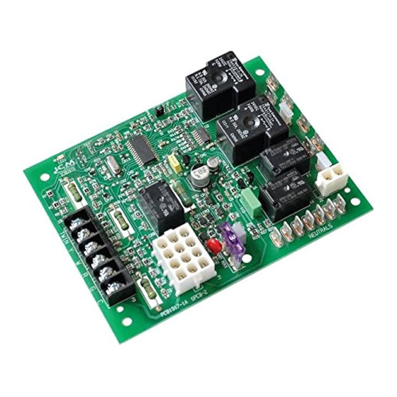
2810
ICM
FURNACE CONTROL BOARD
800.365.5525
LII384
Advertisement
Table of Contents

Related Manuals for ICM Controls ICM2810


Summary of Contents for ICM Controls ICM2810
- Page 1 Twinning: The ICM2810 is Twinning compatible with another ICM2810 control board only. By connecting the designated “TWIN” screw terminals and the 24 VAC common together, the controls are designed to turn on/off the blower simultaneously and at the same speed. (NOTE: An external AC relay, whose coil is connected between R &...
- Page 2 Flame Switches Switches Switches Sensor (N.C.) (N.C.) (N.O.) Probe Twinning with two ICM2810 controls only PIN CONNECTIONS 12-Pin Connections Pin 1 Limit switch (W) (input) Pin 2 Flame sense input Pin 3 24 VAC input Pin 4 Pressure switch (output)
Need help?
Do you have a question about the ICM2810 and is the answer not in the manual?
Questions and answers