Advertisement
Quick Links
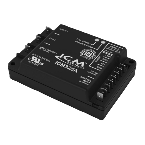
INSTALLATION, OPERATION & APPLICATION GUIDE
For more information on our complete range of American-made products – plus wiring
diagrams, troubleshooting tips and more, visit us at www.icmcontrols.com
FEATURES
• Near field communication using the NFC App
• Inputs for two temperature sensors or two pressure sensors
• Heat pump bypass for full speed operation in heating mode
• Jumper selectable heat active reversing valve enabling
• Jumper selectable control voltage enabling
• Universal input voltage 120-600 VAC
• Universal Control voltage 24-240 VAC (jumper enabled)
CAUTION!
Installation of the ICM325A shall be performed by trained technicians only. Adhere
to all local and national electric codes.
Disconnect all power to the system before making any connections.
SPECIFICATIONS
• Line voltage: 120 - 600 VAC
• Control voltage: 24-240 VAC (Jumper enabled)
• Frequency: 50-60 Hz
• Operating temperature: -40ºF to +176ºF (-40°C to +75°C)
• Temperature sensors: 10K ohms at 77°F (25°C)
• Heat pump reversing valve input: 24-240 VAC (Cool active default / jumper
enabled heat active option)
Note: A maximum of two temperature or two pressure sensors can be connected
to the control.
Note: The ICM325A should be applied to motors and equipment that have
been designated by their respective manufacturers as capable of being speed
controlled.
• Mounting:
– Surface mount using (4) #8 screws
– The ICM325A should be surface mounted to a clean metal or other thermally
conductive surface for maximum heat dissipation
– It is recommended that the ICM325A be mounted away from the condenser
exhaust air in order to maintain lower operating temperatures
CONNECTING THE PROBE
1. Install the temperature probe several bends into the condenser. It can
be attached to the U-bend or placed between the fins in the upper 1/3
of the condenser (see other side for more information).
Note: The response of the system can be fine tuned by repositioning
the probe. Place the probe on the condenser where it is 100°F
when pressures are correct for best response.
2. Connect the two wires from the sensor to the terminal block where it is marked T1/P1. If
additional probes are necessary for multiple refrigerant circuits, they may be attached to
terminals marked T2/P2.
Note: The control will respond to the probe that senses the highest temperature.
OUTPUT VOLTAGE & HARD START SPEED
The minimum output voltage adjusts the range which the control operates in variable
speed. The MAX setting of 48% allows the least amount of modulation over the range
whereas the MIN setting of 17% allows for the most amount of modulation over the range.
The Hard start operates the fan at full speed for a brief period at startup to prevent modulat-
ing the fan on a dry bearing. Both the hard start and minimum output voltage are initially
fixed at midrange by default but can be adjusted using the NFC App.
Universal Communicating Head Pressure Control with Optional Heat Pump Override
With probe temperatures above 100°F, the control applies full voltage to the motor.
The green light (full speed LED) is illuminated indicating full speed operation of the
motor. With probe temperatures between 70°F and 100°F, the motor speed is pro-
portional to the probe temperature. The yellow light is illuminated (variable speed
LED). When the motor starts at temperatures between 70°F and 100°F, it will hard
start for the length of time dictated by the internal software default. After the hard
start time has elapsed, the motor speed is controlled by the probe temperature. As
the temperature being sensed decreases, the output voltage decreases. The output
voltage may decrease to the pre-determined cutout speed dictated by the default
setting in the control's software. System restart will occur when the temperature ex-
ceeds 70°F. With probe temperatures below 70°F, the motor remains off. The green
light and the yellow lights are off.
The HP RV (Heat Pump Reversing Valve) heat pump bypass mode input allows the
ICM325A to determine when the reversing valve on a heat pump is active in heat-
ing which in turn determines if the heat pump is in cooling or heating mode. If in
heating mode, the control bypasses variable speed operation and runs the fan at
full speed to push as much air across the condenser as possible. The ICM325A is
defaulted to cool active reversing valves and a jumper must be placed at the HP RV
enable terminals to allow for heat active reversing valves. Control voltage is enabled
when the control input Jumper is placed. The ICM325A can be used with or without
the control voltage jumper placed. The control voltage input is disabled by default. A
jumper can be placed to enable the control voltage input which allows the ICM325A
to be energized only if the control voltage is present at the control input.
NOTE: The ICM325A is intended to be used with single phase permanent split capac-
itor motors which are capable of having the input voltage varied.
Example
Line 1
Line 2
MODE OF OPERATION
ICM325A TYPICAL INSTALLATION
Motor
Line Voltage
1
Motor
2
Terminal to
be used for
480 VAC
Control
Transformer
Reversing Valve
for Heat Pump
T-Stat
ICM325A
Condenser
The ICM325A can
monitor up to two
condensers
Advertisement

Related Manuals for ICM Controls ICM325A


Summary of Contents for ICM Controls ICM325A
- Page 1 The HP RV (Heat Pump Reversing Valve) heat pump bypass mode input allows the Note: A maximum of two temperature or two pressure sensors can be connected ICM325A to determine when the reversing valve on a heat pump is active in heat- to the control.
- Page 2 Control Voltage 15° 59° 15.7 Wiring of the ICM325A to a heat pump is the same as for air conditioning with the 20° 68° 12.5 exception of the Motor 2 output and the reversing valve input. For a heat pump, the 25°...
Need help?
Do you have a question about the ICM325A and is the answer not in the manual?
Questions and answers