Advertisement
5018419
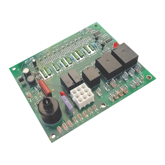
Direct Spark Ignition (DSI) control board
Microprocessor-based
Monitors timing, trial for ignition, system switches, flame sensing and
lockout.
100% lockout safety feature
Compatible with LP or Natural Gas
LED indication for status and fault codes to aid in troubleshooting
The ICM2909 DSI control replaces the following Rheem models: 62-23599(-01,-02,-03,-
04,-05). The ICM2909 has incorporated LED diagnostics to assist in troubleshooting. Fault
code information can be found in this application guide. Please keep this application guide
with the furnace installation manual for future reference.
• Rheem: 62-23599(-01,-02,-03,-04,-05)
Inputs
240 VAC, 50/60 Hz
• Line voltage:
18-30 VAC, 50/60 Hz
• Control voltage:
Vent pressure, limit and MRLC (Manual Reset Limit Control)
• System switches:
Outputs
16FLA/36 LRA @ 240 VAC
• Heat N.C.:
15FLA/30 LRA @ 240 VAC
• Cool N.O.:
4FLA/4LRA @ 240 VAC
• Inducer:
2.3 A PILOT DUTY @ 240 VAC
• Gas valve:
Environmental
-40˚F to 175˚F (-40˚C to 80˚C)
• Operating temperature:
• Storage temperature:
-40˚F to 185˚F (-40˚C to 85˚C)
5% - 95% R.H. (non-condensing) at +55˚C
• Humidity:
6.60" x 5.75" x 2.25"
• Dimensions:
> > > CAUTION < < <
ELECTRICAL SHOCK HAZARD!
off power at the main service panel by removing the fuse or switching the
appropriate circuit breaker to the OFF position. Follow all Local, State and
National Electrical Codes when installing this device.
CAUTION!
Only trained personnel should install or service heating
equipment. When working with heating equipment, be sure to read and
understand all precautions in the documentation, on labels, and on tags that
accompany the equipment. Failure to follow all safety guidelines may result in
damage to equipment, severe personal injury or death.
Flashes
Fault Condition
Normal operation
ON solid
No power or incorrect gas valve wiring
OFF
Flame loss or ignition failure lockout
1
Pressure switch stuck open or stuck
2
closed
Limit switch open
3
Flame detected with gas valve closed
4
Manual Reset Limit Control is open
5
Internal Error
6
Features
Introduction
Replaces
Specifications
Before installing this unit, turn
Fault Codes, STATUS LIGHTS AND TROUBLESHOOTING
CAUTION!
to do so may result in wiring errors that can cause dangerous operation.
1. Turn thermostat to the OFF position or set it to the lowest possible setting.
2. Turn OFF the electrical supply to furnace.
3. Turn OFF the gas supply to furnace.
CAUTION!
fire, death or personal injury.
4. Remove the furnace blower and control access doors.
5. Disconnect the thermostat wires and humidifier wires (if equipped with a humidifier).
6. Disconnect the line voltage, blower, electronic air cleaner wires (if equipped) and
transformer wires.
7. Remove screws and any other fasteners and the old circuit board.
8. Examine the control and the control box for water stains.
9. Make repairs if any sources of water leakage are found. Be sure to check humidifiers,
evaporator coils and vent systems in the area of the control.
1. Ground yourself. When handling the circuit board; hold it by the edges.
2. Fasten the circuit board with the retaining screws.
3. Connect all line voltage, low voltage and accessory wires.
4. Verify the sequence of operation.
When a W call is received from the thermostat; the control shall perform a hardware safety
check before progressing with the heat sequence. If no issues are detected during the
hardware safety check; the Inducer Draft motor is energized. The Vent Pressure switch
closes. Ignition sequence begins; gas valve and spark are engaged, providing the system
safety switches (Limit and MRLC) are closed. The Blower motor will engage at the HEAT
speed 30 seconds after flame is established and sensed. Once the W call has been
satisfied; the Inducer motor turns off after 5 seconds and the blower motor turns off after 90
seconds.
A G call from the thermostat will engage the blower motor without delay at the HEAT speed.
It disengages without delay when the G call is removed.
A Y call from the thermostat will engage the blower motor without delay at the COOL
speed. It disengages 30 seconds after the Y call is satisfied.
Flame not established
1. If flame is not established during the 7 second initial sequence then the control will start
the next trial for ignition in 60 seconds.
2. There will be 2 more attempts to ignite, 60 seconds apart before the respective fault
code is triggered and ignition trials are stopped.
3. The gas valve is energized only during the ignition sequence of 7 seconds.
4. The blower motor is off until 30 seconds after flame is established.
Flame out
1. Flame out is considered when flame is lost during the heating cycle.
2. When a signal is present on W and flame is not sensed; the gas valve will disengage
until the next trial for ignition
3. The inducer motor will continue running during flame out scenario and the blower motor
will turn off after the 90 second post purge.
Flame out of sequence
1. Flame out of sequence represents a scenario where flame is sensed while the W signal
is not present.
2. Inducer and Blower motors will be engaged (if not already running) and will continue
running for as long as the fault condition is present.
3. There is 60 minute lockout before a W call can be executed or on power reset
Trouble Shooting
Normal
Check for 24VAC to the board,check door switch, check supply transformer primary and secondary voltage, make sure gas
valve is wired correctly and grounded properly.
Flame was lost or the number of retry's or recycles has exceeded the limit for the control. Clean or replace the flame sensor,
check the igniter for proper operation & input voltage, check the transformer's common is grounded to earthground
Check for obstructed pressure switch tubing or defective pressure switch. Check for oxidation on terminals, broken wires, or
defective inducer motor. Check for proper voltage at the inducer motor input.
Check for blocked airflow, blocked duct work and dirty filter. Check or replace high limit switch if defective.
Flame was sensed when no flame is present. Check or replace flame sensor and check the grounds.
Check for plugged flue pipe, check for cracked heat exchanger, check for flame rollout.
Internal board failure, replace control board
Direct Spark Ignition (DSI) control board
Remove Existing Control
To service control, and prior to disconnection, label all wires. Failure
Failure to turn off gas and electric supplies can result in explosion,
Install New Control
Sequence of Operation
Flame Sense Troubleshooting Tips
2909
ICM
LIAF299-1
Advertisement
Table of Contents

Related Manuals for ICM Controls ICM2909


Summary of Contents for ICM Controls ICM2909
- Page 1 The ICM2909 DSI control replaces the following Rheem models: 62-23599(-01,-02,-03,- hardware safety check; the Inducer Draft motor is energized. The Vent Pressure switch 04,-05). The ICM2909 has incorporated LED diagnostics to assist in troubleshooting. Fault closes. Ignition sequence begins; gas valve and spark are engaged, providing the system code information can be found in this application guide. Please keep this application guide safety switches (Limit and MRLC) are closed.
- Page 2 Limit switch open Pin 8 MRLC (Manual Reset Limit Control) output Pin 9 Flame sense Flame detected with gas valve closed MRLC (Manual Reset Limit Control) open Internal Error Wiring Diagram ICM2909 LED 1 MOV1 L1/R1 HEAT COOL L2/C1 UNUSED...
Need help?
Do you have a question about the ICM2909 and is the answer not in the manual?
Questions and answers