Advertisement
ICM326HN / ICM327HN
Line Voltage Head Pressure Control
With built-in transformer Optional heat pump override
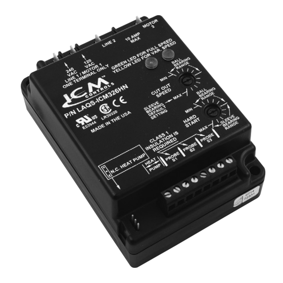
ICM326HN
Installation of the ICM326HN and ICM327HN shall be performed by trained technicians only. Adhere to all
local and national electric codes.
Disconnect all power to the system before making any connections.
Specifications
• Line voltage: 120, 208/240, and 480 VAC
• Frequency: 50-60 Hz
• Output: 10 amp maximum, 100 mA minimum
• Operating temperature: -40ºF to +176ºF (-40°C to +75°C)
• Sensors: 10K ohms at 25°C
• Heat pump override: N.C. or N.O.
Note: A maximum of three sensors can be connected to the control
• Weight: 12 ounces (341 grams)
Note: The ICM326HN and ICM327HN should be applied to motors and equipment that have been designated
by their respective manufacturers as capable of being speed controlled
• Mounting:
– Surface mount using (4) #8 screws
– The ICM326HN and ICM327HN should be surface mounted to a clean metal or other thermally-conductive
surface for maximum heat dissipation
– It is recommended that the ICM326HN and ICM327HN be mounted away from the condenser exhaust air to
maintain lower operating temperatures
ELECTRICAL SHOCK HAZARD – Installation of the ICM326HN and ICM327HN shall be performed by
trained technicians only. Adhere to all local and national electric codes. Disconnect all power to the system
before making connections.
Connections for ICM326HN at 120 VAC
1. Remove power from system.
2. Field install a wire from Line 1 wire to Line 1 terminal.
3. Cut Line 2 wire; affix motor side to Motor 2 terminal
and line side to Line 2 terminal.
4. Make 24 VAC and temperature probe connections.
5. Verify wiring is correct.
6. Power up system and check operation.
120 VAC
Field
Installed
Wire
Line
1
120 VAC
Connections for Heat Pump System at 208/240 VAC
1. Remove power from system.
2. Field install a wire from Line 1 wire to Line 1 terminal.
3. Cut Line 2 wire; affix the common from the defrost
board's fan relay to the Motor 2 terminal and the Line
from the contactor to the Line 2 terminal.
208/240
VAC
Field
Installed
Wire
Line
1
240 VAC
ICM327HN
Caution!
120 VAC
Run
Capacitor
Typical
condenser fan
Run
Capacitor
Line
Motor
2
2
4. Make 24 VAC, probe and HP connections.
5. Verify wiring is correct.
6. Power up system and check operation.
Fan
Relay
COM
Defrost Board
Run
Capacitor
Line
Motor
2
2
1. Remove power from system.
2. Field install a wire from Line 1 wire to Line 1 terminal.
3. Cut Line 2 wire; affix motor side to Motor 2 terminal
and line side to Line 2 terminal.
4. Make 24 VAC and temperature probe connections.
5. Verify wiring is correct.
6. Power up system and check operation.
Connections for Heat Pump System at 480 VAC
1. Remove power from system.
2. Field install a wire from Line 1 wire to Line 1 terminal.
3. Cut Line 2 wire; affix the common from the defrost
board's fan relay to the Motor 2 terminal and the Line
from the contactor to the Line 2 terminal.
1. Install the temperature probe several bends into the condenser. It can be attached to the
U-bend or placed between the fins in the upper 1/3 of the condenser (see other side for
more information).
Note: The response of the system can be fine tuned by repositioning the probe. Place
the probe on the condenser where it is 100°F when pressures are correct for
best response.
2. Connect the two wires from the sensor to the terminal block where it is marked PROBE S1.
If additional probes are necessary for multiple refrigerant circuits, they may be attached to
terminals marked PROBE S2 and PROBE S3.
Note: The control will respond to the probe that senses the highest temperature.
1. For non-heat pump applications, the heat
pump select jumper must be in the Default
(N.O.) position, and the HP terminals must be left
unconnected.
PSC
Fan
Motor
PSC
Fan
Motor
Connections for Heat Pump Systems
Note: HP terminals will not recognize 24 VAC. Line voltage must be applied (120, 208/240, or 480 VAC).
1. The heat pump terminals accept the line voltage signal from the reversing valve holding coil. Make a parallel
connection from the reversing valve to HP terminals.
2. If the heat pump is in the Heating mode and the reversing valve is energized, then the Heat Pump
Select jumper must be in the Default (N.O.) position.
3. If the heat pump is in the Heating mode and the reversing valve is not energized, then the Heat
Pump Select jumper must be in the
NC
PSC
Fan
Motor
Connections for ICM327HN at 480 VAC
Typical
condenser fan
480 VAC
Field
Installed
Wire
Line
Line
Motor
1
2
2
480 VAC
4. Make 24 VAC, probe and HP connections.
5. Verify wiring is correct.
6. Power up system and check operation.
480 VAC
Field
Installed
Wire
Line
Line
Motor
1
2
2
480 VAC
Connecting the Probe
Connections for Air Conditioning Only
Heat Pump
Select Jumper
Default Position
N.C. position.
Probe S3
Probe S2
Probe S1
HP
Heat Pump
Select Jumper
Default Position
RV
Connect Parallel to
Reversing Valve
Run
Capacitor
PSC
Fan
Motor
Run
Capacitor
PSC
Fan
Motor
Fan
Relay
COM
NC
Defrost Board
Run
Capacitor
PSC
Fan
Motor
Example
Probe S3
Probe S2
Probe S1
HP
Temperature
Probe
N.O.
N.C.
Temperature
Probe
Advertisement
Table of Contents

Related Manuals for ICM Controls ICM326HN


Summary of Contents for ICM Controls ICM326HN
- Page 1 6. Power up system and check operation. board’s fan relay to the Motor 2 terminal and the Line from the contactor to the Line 2 terminal. Caution! 480 VAC Installation of the ICM326HN and ICM327HN shall be performed by trained technicians only. Adhere to all Field local and national electric codes. Installed Wire Disconnect all power to the system before making any connections.
- Page 2 113° the RPM level of the condenser fan. Set the Cutout Speed dial according to the type of motor you have. 50° 122° Sleeve Bearing Motors: Set the Cutout Speed dial to the middle of the sleeve bearing range. In this range, the motor can run down approximately 40-50% of the full line voltage, which allows sufficient RPMs for cooling and lubrication. CAUTION!: With sleeve bearing motors, it is important not to ICM326HN Typical Installation adjust outside the sleeve bearing range or bearing failure may result. Ball Bearing Motors: t o r L i n Set the Cutout Speed dial to the MIN position in the ball bearing range. This position offers the greatest range of L i n e 1 t o r e 2 speed control. At the MIN setting the motor can run down to approximately 20-30% of the full line voltage.
Need help?
Do you have a question about the ICM326HN and is the answer not in the manual?
Questions and answers