Advertisement
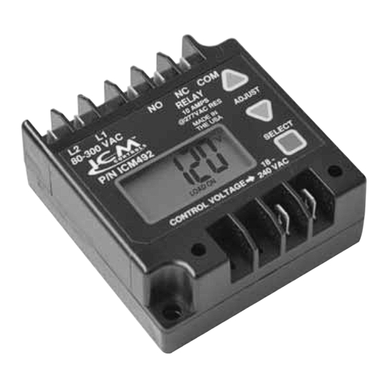
ICM492
Reliable protection of single phase systems against adverse line voltage conditions
DESCRIPTION
The ICM492 is specifically designed to monitor line
voltage and guard single phase equipment against
damage caused by under and over line voltage
conditions and rapid short cycling. Records last five
faults.
SPECIFICATIONS
User Adjustable Settings:
• Voltage setpoint: 95-280V
• Anti-short cycle time delay: 0-720 sec.
• Over voltage setting: 5-25%
• Under voltage setting: 5-25%
• Control mode: On and Off
• Response time: 0.1 to 10 seconds
Inputs:
• Line voltage: 80 to 300 VAC
• Control voltage: 24 to 240 VAC
• Frequency: 50/60 Hz
• Accuracy: ±2%
• Low power consumption: Max 50 mA @ 120V,
Output:
• Type: dry relay contacts
• Form: SPDT
• Relay contact ratings:
– N.C. Contacts: 10A resistive @ 277 VAC
– N.O. Contacts: 10A resistive @ 277 VAC
• Connection Terminals: 0.25" male fast-on
Mechanical:
• Case dimensions: 3"L x 3.2"W x 1.35"H
• Unit weight: 0.36 lbs.
Environmental:
• Operating temp. range: -30°C to +70°C
• Storage temp. range: -40°C to +85°C
• Maximum operating/storage relative humidity:
95% non-condensing
LII335-3
Single Phase Digital Line Voltage Monitor
Max 100 mA @ 240V
7313 William Barry Blvd., North Syracuse, NY 13212
(Phone) 315-233-5266 (Toll Free) 800-365-5525
(Fax) 315-233-5276
www.icmcontrols.com
Constantly monitors and displays line
voltage. Protects against Over and Under
voltage, and Rapid Short Cycling caused by
Transient Faults and Power Interruptions
FEATURES
• Universal Line Voltage
Input
• Easy-view Backlit Digital
Display
• RMS Voltage Monitoring
• 5-fault memory storage
• Adjustable Voltage Set
Point
• Adjustable Over Voltage
Set Point
• Adjustable Under
Voltage Set Point
MODE OF OPERATION
The ICM492 continuously monitors incoming line voltage
for faults and displays RMS voltage on the digital
display. When line voltage is appropriate, ICM492 closes
the COM and N.O. relay contacts. When incoming line
voltage is outside of user selected parameters, ICM492
will close the COM and N.C. relay contacts and indicate
a fault condition by flashing FAULT on display. The unit
records the last five faults, storing the highest and lowest
voltage readings that caused the fault. The UP, DOWN
and SELECT buttons are pressed simultaneously to
clear the faults from memory. The SELECT menu has
the following user adjustable settings: voltage set point,
time delay, over voltage percentage, under voltage
percentage, control mode, and response time. Time
delay prevents short cycling when fault no longer is
present and rapid power interruptions. The response
time on the fault condition can be adjusted to help
reduce nuisance trips from transient faults. When
Control Mode setting is selected ON then ICM492 will
close COM and N.O. relay contacts only when control
voltage is present at Control Voltage terminals and the
line voltage is good. The relay contacts can be used
to direct drive the load as long as current rating is not
exceeded.
!!! WARNING !!!
Electrical Shock Hazard
• Verify power is disconnected by removing a fuse
or opening a circuit breaker before making any
connections.
• This control should be installed by a trained technician.
• Incorrect installation can cause personal injuries,
property damage or death.
• Follow all local & national codes while installing control.
• Adjustable Anti-Short
Cycle Time Delay
• Adjustable Response on
Fault Time
• Control Mode
• 5-Fault Memory
• Universal Control
Voltage Input
• Heavy Duty SPDT Relay
Output
Advertisement
Table of Contents

Related Manuals for ICM Controls ICM492


Summary of Contents for ICM Controls ICM492
- Page 1 ICM492 Single Phase Digital Line Voltage Monitor Reliable protection of single phase systems against adverse line voltage conditions Constantly monitors and displays line voltage. Protects against Over and Under voltage, and Rapid Short Cycling caused by Transient Faults and Power Interruptions FEATURES • Universal Line Voltage...
- Page 2 !!! DANGER !!! Verify power is disconnected by removing a fuse or opening a circuit breaker before making any connections or injury or death can result. 1. Disconnect power. 2. Mount ICM492 securely against the metal chaises of the system in a water proof environment. 3. If a contactor or a relay is used in the system (see Fig.1) to control power to the load then: a. Make L1 and L2 connections. b. Cut the wire that powers the contactor/relay coil, strip and place 1/4” female spade terminals on them. c. Plug female spade terminals on COM and N.O. terminals of ICM492. 4. Should you choose to drive the load directly (see Fig.2) using relay contacts of ICM492 then: a. Make sure that load current rating does not exceed current rating of ICM492 relay contacts. b. Cut the line that powers the load, strip and place 1/4” female spade terminals on them. c. Plug female spade terminals on COM and N.O. terminals of ICM492. 5. Should you choose to use a control signal at Control Voltage input terminals then: a. Use two wires with 1/4”female spade terminals on them to plug on Control Voltage terminals of ICM492.
Need help?
Do you have a question about the ICM492 and is the answer not in the manual?
Questions and answers