Table of Contents
Advertisement
Quick Links
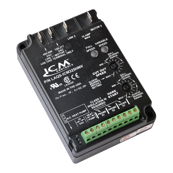
ICM325HNV
High Voltage Head Pressure Control with
Optional Heat Pump Override
Temperature sensitive control regulates head pressure
Installation, Operation & Application Guide
For more information on our complete range of American-made
products – plus wiring diagrams, troubleshooting tips and more,
visit us at www.icmcontrols.com
Installation of the ICM325HNV shall be performed by trained technicians only. Adhere to all local and national electric codes.
Disconnect all power to the system before making any connections.
• Line voltage: 120-600 VAC
• Control voltage: 18-30 VAC
• Frequency: 50-60 Hz
• Operating temperature: -40ºF to +176ºF (-40°C to +75°C)
• Sensors: 10K ohms at 77°F (25°C)
• Heat pump override: 24 VAC N.C. or N.O.
Note: A maximum of three sensors can be connected to the control.
• Weight: 12 ounces (341 grams)
Note: The ICM325HNV should be applied to motors and equipment that have been designated by their respective manufacturers as capable of being speed controlled.
• Mounting:
– Surface mount using (4) #8 screws
– The ICM325HNV should be surface mounted to a clean metal or other thermally conductive surface for maximum heat dissipation
– It is recommended that the ICM325HNV be mounted away from the condenser exhaust air in order to maintain lower operating temperatures
Connections for ICM325HNV at 120/208/240 VAC
1. Remove power from system.
2. Field install a wire from Line 1 wire to Line 1 terminal.
3. Cut Line 2 wire; affix motor side to Motor 2 terminal
and line side to Line 2 terminal.
4. Make 24 VAC and temperature probe connections.
5. Verify wiring is correct.
6. Power up system and check operation.
120/208/240
VAC
Field
Installed
Wire
Line
1
120/240
VAC
Connections for Heat Pump System at 120/208/240 VAC
1. Remove power from system.
2. Field install a wire from Line 1 wire to Line 1 terminal.
3. Cut Line 2 wire; affix the common from the defrost
board's fan relay to the Motor 2 terminal and the Line
from the contactor to the Line 2 terminal.
120/208/240
VAC
Field
Installed
Wire
Line
1
120/240
VAC
Connecting the Probe
1. Install the temperature probe several bends into the condenser. It can be
attached to the U-bend or placed between the fins in the upper 1/3 of the
condenser (see other side for more information).
Note: The response of the system can be fine tuned by repositioning the
probe. Place the probe on the condenser where it is 100°F when
pressures are correct for best response.
2. Connect the two wires from the sensor to the terminal block where it is marked PROBE S1. If
additional probes are necessary for multiple refrigerant circuits, they may be attached to terminals
marked PROBE S2 and PROBE S3.
Note: The control will respond to the probe that senses the highest temperature.
120/208/240
Run
VAC
Capacitor
Typical
condenser fan
Run
Capacitor
Line
Motor
2
2
4. Make 24 VAC, probe and HP connections.
5. Verify wiring is correct.
6. Power up system and check operation.
Fan
Relay
COM
Defrost Board
Run
Capacitor
Line
Motor
2
2
Caution!
Specifications
Wiring Diagrams
1. Remove power from system.
2. Field install a wire from Line 1 wire to Line 1 terminal.
3. Cut Line 2 wire; affix motor side to Motor 2 terminal
and line side to Line 2 terminal.
PSC
4. Make 24 VAC and temperature probe connections.
Fan
5. Verify wiring is correct.
Motor
6. Power up system and check operation.
PSC
Fan
Motor
Connections for Heat Pump System at 480 VAC
1. Remove power from system.
2. Field install a wire from Line 1 wire to Line 1 terminal.
3. Cut Line 2 wire; affix the common from the defrost
board's fan relay to the Motor 2 terminal and the Line
from the contactor to the Line 2 terminal.
NC
PSC
Fan
Motor
1. For non-heat pump applications,
the heat pump select jumper must
be in the Default (N.O.) position,
and the HP terminals must be left
unconnected.
Example
2. Set the Cutout Speed and the
Hard Start Time to the appropriate
positions for the type of motor you
have (see other side).
Connections for ICM325HNV at 480 VAC
Typical
condenser fan
480 VAC
Field
Installed
Wire
Line
Line
Motor
1
2
2
480 VAC
4. Make 24 VAC, probe and HP connections.
5. Verify wiring is correct.
6. Power up system and check operation.
480 VAC
Field
Installed
Wire
Line
Line
Motor
1
2
2
480 VAC
Connections for Air Conditioning Only
Additional
Probes
Probe S1
Heat Pump
HP
Select Jump-
er Default
Position
24 VAC
Run
Capacitor
PSC
Fan
Motor
Run
Capacitor
PSC
Fan
Motor
Fan
Relay
COM
NC
Defrost Board
Run
Capacitor
PSC
Fan
Motor
Temperature Probe
Advertisement
Table of Contents

Related Manuals for ICM Controls ICM325HNV


Summary of Contents for ICM Controls ICM325HNV
- Page 1 • Heat pump override: 24 VAC N.C. or N.O. Note: A maximum of three sensors can be connected to the control. • Weight: 12 ounces (341 grams) Note: The ICM325HNV should be applied to motors and equipment that have been designated by their respective manufacturers as capable of being speed controlled. • Mounting: – Surface mount using (4) #8 screws – The ICM325HNV should be surface mounted to a clean metal or other thermally conductive surface for maximum heat dissipation...
- Page 2 77° 10.0 pressures are correct is ideal. 30° 86° 35° 95° 40° 104° 45° 113° 50° 122° ONE-YEAR LIMITED WARRANTY ICM325HNV Typical Installation The Seller warrants its products against defects in material or workmanship for a period of one (1) year from the date of manufacture. The liability of the Seller is limited, at its option, to repair, replace or issue a non-case credit for the purchase prices of the goods which are provided to be defective. The warranty and remedies set forth herein do not apply to any goods or parts thereof which have been subjected to misuse including any use or application in violation of the Seller’s instructions, neglect, tampering, improper storage, incorrect installation or servicing not performed by the Seller. In order to permit the Seller to properly administer the warranty, the Buyer shall: 1) Notify the Seller promptly of any claim, submitting date code information or any other pertinent data as requested by the Seller. 2) Permit the Seller to inspect and test the product claimed to be defective. Items claimed to be defective and are determined by Seller to be non-defective are subject to a $30.00 per hour inspection fee. This warranty constitutes the Seller’s sole liability hereunder and is in lieu of any other warranty expressed, implied or statutory. Unless otherwise stated in writing, Seller makes no warranty that the goods depicted or described herein are fit for any particular purpose. 7313 William Barry Blvd., North Syracuse, NY 13212 (Toll Free) 800-365-5525...
Need help?
Do you have a question about the ICM325HNV and is the answer not in the manual?
Questions and answers