Table of Contents
Advertisement
Quick Links
www.larius.com
56500/6
JOLLY frame - 220 bar - motor 110V
K56500/6
JOLLY frame - 220 bar - motor 110V + gun
56500/5
JOLLY frame - 220 bar - motor 220V
K56500/5
JOLLY frame - 220 bar - motor 220V + gun
IT
https://www.larius.com/wp-content/uploads/JOLLY_I.pdf
EN
https://www.larius.com/wp-content/uploads/JOLLY_GB.pdf
DE
https://www.larius.com/wp-content/uploads/JOLLY_D.pdf
Electric Piston Airless Pump
56501/5
JOLLY trolley - 220 bar - motor 110V
K56501/5
JOLLY trolley - 220 bar - motor 110V + gun
56501/4
JOLLY trolley - 220 bar - motor 220V
K56501/4
JOLLY trolley - 220 bar - motor 220V + gun
ES
https://www.larius.com/wp-content/uploads/JOLLY_E.pdf
FR
https://www.larius.com/wp-content/uploads/JOLLY_F.pdf
EN
Jolly
Advertisement
Table of Contents

Related Manuals for Samoa Jolly 56501/5


Summary of Contents for Samoa Jolly 56501/5
- Page 1 www.larius.com Electric Piston Airless Pump Jolly 56501/5 JOLLY trolley - 220 bar - motor 110V K56501/5 JOLLY trolley - 220 bar - motor 110V + gun 56501/4 JOLLY trolley - 220 bar - motor 220V K56501/4 JOLLY trolley - 220 bar - motor 220V + gun 56500/6 JOLLY frame - 220 bar - motor 110V K56500/6...
- Page 2 This manual is to be considered as an English language translation of the original manual in Italian. The manufacturer shall bear no responsibility for any damages or inconveniences that may arise due to the incorrect translation of the instructions contained within the original manual in Italian. Due to a constant product improvement programme, the factory reserves the right to modify technical details mentioned in this manual without prior notice.
-
Page 3: Table Of Contents
WE ADVISE THE USE OF THIS EQUIPMENT ONLY BY PROFESSIONAL OPERATORS. ONLY USE THIS MACHINE FOR USAGE SPECIFICALLY MENTIONED IN THIS MANUAL. Thank you for choosing a SAMOA. product. As well as the product purchased, you will receive a range of support services enabling you to achieve the results desired, quickly and professionally. -
Page 4: Awarnings
JOLLY WARNINGS The table below provides the meaning of the symbols used in this manual in relation to using, earthing, operating, maintaining, and repairing of this equipment. • Read this operator’s manual carefully before using the equipment. • An improper use of this machine can cause injuries to people or things. •... -
Page 5: Btransport And Unpacking
JOLLY TRANSPORT SAFETY RULES AND UNPACKING • THE EMPLOYER SHALL TRAIN ITS EMPLOYEES ABOUT ALL THOSE RISKS STEMMING FROM ACCIDENTS, ABOUT • The packed parts should be handled as indicated in the THE USE OF SAFETY DEVICES FOR THEIR OWN SAFE- symbols and markings on the outside of the packing. - Page 6 JOLLY • TIGHTEN AND CHECK ALL THE FITTINGS FOR CONNEC- TION BETWEEN PUMP, FLEXIBLE HOSE AND SPRAY GUN Take proper safety measures for the protection BEFORE USING THE EQUIPMENT. of hearing in case of work near the plant. • ALWAYS USE THE FLEXIBLE HOSE SUPPLIED WITH STAN- DARD KIT.
-
Page 7: Eworking Principle
JOLLY WORKING PRINCIPLE INDICATIONS OF USE The JOLLY unit is defined “electric piston pump”. An electric piston pump is used for high pressure painting without To ensure correct operation of the airless electric piston equipment the “minimum power requirements” must be respected. The use air (from this process derives the term ”airless”). -
Page 8: Ftechnical Data
JOLLY TECHNICAL DATA JOLLY Max. delivery 1,9 l/m Max working pressure 220 bar Motor power 0,7 Kw 110 VAC Voltage 220 VAC Weight 15 Kg - frame / 16Kg trolley Max. nozzle size 0,021” Power generation 4 Kw Single phase Material outlet 1/4”... -
Page 9: Gdescription Of The Equipment
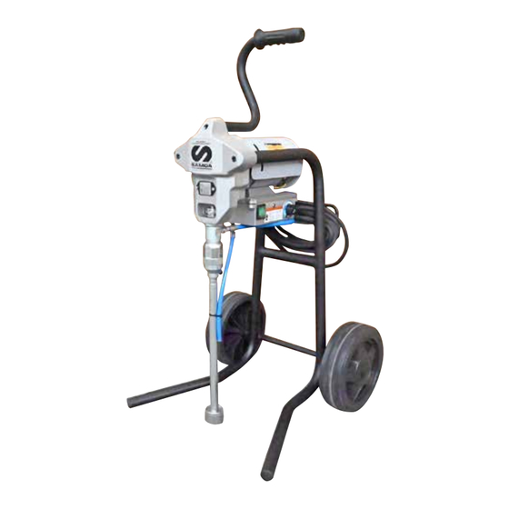
JOLLY DESCRIPTION OF THE EQUIPMENT Version on FRAME Fig. 1 Pos. Description Pos. Description Recirculation tube Alarms indicator light Output product recirculation Airless manual gun Safety-recirculation valve Trigger safety clamp Suction filter Reduction box Plug filter Handle/Handgrip Pumping group Frame ON/OFF switch Unlocking manual device Potentiometer for adjusting the operating pressure... - Page 10 JOLLY Version on TROLLEY Press here to unlock Fig. 2 Pos. Description Pos. Description Trolley Product delivery tube coupling Suction tube Unlocking manual device Recirculation hose Electric motor Wheel Product delivery tube REV. 08 - 11/2024 - Cod. 150165...
-
Page 11: Hpipe Connection
JOLLY PIPE CONNECTION CHECK ON POWER SUPPLY Make sure that the electrical system is earthed CONNECTING THE FLEXIBLE HOSE TO THE GUN and complies with regulations. • Connect the high pressure flexible hose (1) to the pump (2) and to the gun (3) ensuring to tighten the fittings (the use of two wrenches is suggested). - Page 12 JOLLY CONNECTING THE EQUIPMENT TO THE POWER SUPPLY • Lift the suction group and dip it into the tank containing the washing liquid. Check that the switch (H5) is on the “OFF” (0) position before • • Press the equipment main switch (5) on pos. “ON” (I). connecting the cable to the mains.
-
Page 13: Preparation Of The Paint
JOLLY • Turn the pressure regulating knob (6) clockwise to the position • Point the gun (3) into a collecting tank (8) keeping the trigger “RECIRCULATION AND WASHING” (see drops) so that the pressed (so as to drain the oil inside) till a clean solvent comes machine idles. -
Page 14: Ioperation
JOLLY OPERATION • Open the recirculating-safety valve (2) (turn clockwise so as the pin slides on the cam track). START OF THE PAINTING OPERATIONS • Use the equipment only after performing all the SETTING UP operations described above. • Dip the suction pipe (1) into the product tank. Version on FRAME Fig. -
Page 15: Procedure To Unlock The Suction Group Ball
JOLLY PROCEDURE TO UNLOCK THE SUCTION GROUP BALL • Close the recirculating-safety valve (2) (turn clockwise to release the valve). Should the ball of the suction group be blocked, the unit does not suck the product anymore. Procedere to manually release the ball as follows: •... -
Page 16: Jcleaning At The End Of The Work
JOLLY CLEANING AT THE END OF ALLARMI - ALARMS WARNMELDUNGEN - ALARME THE WORK CORRENTE MASSIMA SUPERATA • Reduce pressure to the minimum (turn counterclockwise the MAXIMUM CURRENT EXCEEDED pressure control knob) (1). MAX. STROM ÜBERSCHRITTEN • Press the switch (2) placed on the box of the electric motor, MAXIMUM COURANT DÉPASSÉE to stop the equipment. -
Page 17: Kgeneral Maintenance
JOLLY ROUTINE MAINTENANCE CHECK ON THE PACKING NUT Daily check the packing nut is tight in order to avoid wastes but not excessively to prevent the piston from seizing and the gaskets from wearing. • For tightening, use the wrench supplied (ref. 11503). Rif. -
Page 18: Mwarning Plates
JOLLY WARNING PLATES REV. 08 - 11/2024 - Cod. 150165... -
Page 19: Ncorrect Procedure Of Decompression
JOLLY CORRECT PROCEDURE • Disconnect the power supply cable (4). OF DECOMPRESSION • Insert the gun clamp (1). Clamp released Fig. 3 • Release the gun clamp (1), point the gun into the tank of the Clamp inserted product and press the trigger to release pressure. At the end of the operation, insert the gun clamp. -
Page 20: Oreplacement Of The Pumping Group's Gaskets
JOLLY REPLACEMENT OF THE PUMPING GROUP’S GASKETS • It is recommended to perform this operation after having • Remove the locking pin (5) using pliers (6). cleaned the equipment. Always disconnect the power supply and di- scharge pressure before performing the following operations (follow the “correct procedure of decompression”). -
Page 21: Pit Stop Maintenance
JOLLY • Disconnect the pumping group by unscrewing the fastening • Use a 36 mm spanner to unscrew the pump unit as shown. nut (wrench 45). • Unscrew the pumping group from the housing. You can now work easily as the pump casing has been freed. •... - Page 22 JOLLY REPLACING THE FOOT VALVE SEALS • Unscrew the gasket ring nut (20) completely. • Replace the PTFE gasket (15) located under the ball housing All the gaskets in the unit must be replaced at the same (16). time to ensure a correct operation of the equipment. •...
- Page 23 JOLLY • Remove the kit of gaskets contained inside the pump unit housing, as shown. Fig. 16 Fig. 18 Upper white PTFE Grey polyethylene Waxed leather Grey polyethylene Inferior white PTFE Steel female ring Code 16106 PTFE white Code 16107 Polyethylene grey Code 16124 •...
-
Page 24: Replacing The Pump Unit Stem Gasket
JOLLY • Remove the PTFE O-ring (23) and replace it with a new one • Use a 10 mm spanner to unscrew and remove the stem (19) (24). as indicated. • Remove the complete gasket kit (25) from the stem (19), as shown, in order to replace it. - Page 25 JOLLY • Replace the scraper ring (26) of the valve piston, as shown in the picture. • Check the surfaces of the ball (27) and ball housing (P28), and replace both if damaged. Fig. 24 Fig. 25 • Assemble the components as shown. Steel male ring Code 18644 Fig.
- Page 26 JOLLY • Insert the stem (19) into the housing (18) while rotating it in • Use a 36 mm spanner to screw the pump unit (10). order to allow it to slide more easily and to avoid damaging the upper gaskets. Fig.
-
Page 27: Correct Positioning Of The Pump Unit
JOLLY CORRECT POSITIONING OF THE PUMP UNIT • Use a gauge to measure the gap between the base of the template and the tightening groove. Once the unit has been refitted, proceed as follows: • Check the position of the rod, which should be positioned at its lower stopping point. - Page 28 JOLLY • Once the unit has been correctly positioned, tighten the lock For correct reassembly, see the drawing of the nut (37) hard against the front template. pump unit, and follow disassembly operations To tighten, use a 45 mm spanner. in reverse order.
-
Page 29: Electric Motor Brush Replacement
JOLLY ELECTRIC MOTOR BRUSH REPLACEMENT WARNING: Always indicate code and quantity for each part required. BRUSHES CHECK DISCONNECT THE POWER SUPPLY BEFORE CHECKING OR REPLACING THE BRUSHES. • Periodically check the wear of the brushes (at least every 250 working hours). •... - Page 30 JOLLY BRUSH Ref. 56570 *Length of the new brush **Minimum length of the brush REPLACE REV. 08 - 11/2024 - Cod. 150165...
-
Page 31: Troubleshooting
JOLLY TROUBLESHOOTING Problem Cause Solution The equipment does not start Lack of voltage; Check the correct connection to the power supply; Considerable drops in mains voltage; Check the extension cable; On/Off switch disconnected; Ensure the On/Off switch is on the “on” position and turn clockwise the pressure control knob;... -
Page 32: Spare Parts
JOLLY SPARE PARTS version on frame Complete electromechanical Frame Electric motor brush group page 35 page 43 page 36 Complete hydraulic group page 38 Suction and recirculation kit on frame page 42 Complete electro-hydraulic Line filter control device page 44 page 40 REV. - Page 33 JOLLY SPARE PARTS version on trolley Trolley page 34 Suction and recirculation kit on trolley page 36 REV. 08 - 11/2024 - Cod. 150165...
- Page 34 JOLLY REV. 08 - 11/2024 - Cod. 150165...
-
Page 35: Rframe
JOLLY FRAME REF. 56564 WARNING: Always indicate code and quantity for each part required. Pos. Code Description Pos. Code Description 37406 Screw 56564 Frame unit 34009 Washer 21654 Handle 37403 Foot 50526 Handgrip 37177 Screw 56527 Right frame-tube 56528 Left frame-tube REV. -
Page 36: Complete Electro-Mechanical Group
JOLLY COMPLETE ELECTRO-MECHANICAL GROUP REF. 56560 FOR ALL VERSIONS WARNING: Always indicate code and quantity for each part required. COMPLETE HYDRAULIC GROUP REF. 56562 REV. 08 - 11/2024 - Cod. 150165... - Page 37 JOLLY Pos. Code Description Pos. Code Description 18666 56560 Complete electro-mechanical group 18674 Safety cover 56572 Nut Cover 18677 Label 56522 Motor cover 5378 Screw 56524 Warning label 18664 Rod bushing 56575 Electric motor 220V 50Hz 18685 Ring 56575/1 Electric motor 110V 50Hz 18665 Spring 18667...
-
Page 38: Complete Hydraulic Group
JOLLY COMPLETE HYDRAULIC GROUP REF. 56562 WARNING: Always indicate code and quantity for each part required. REV. 08 - 11/2024 - Cod. 150165... - Page 39 JOLLY Pos. Code Description Pos. Code Description 9288 Spring 56562 Complete hydraulic group 56547 Releasing rod complete 16109 Ring packing 56539 Command rod 16127 Locking nut 56537 Releasing rod 16105 Upper gaskets kit 56538 Guiding bushing 16106 Ring 56541 Nut M6 stopper 16107 PTFE gasket 18652...
-
Page 40: Complete Electro-Hydraulic Driving Group
JOLLY COMPLETE ELECTRO-HYDRAULIC DRIVING GROUP REF. 56561 FOR ALL VERSIONS WARNING: Always indicate code and quantity for each part required. REV. 08 - 11/2024 - Cod. 150165... - Page 41 JOLLY Pos. Code Description Pos. Code Description 18693/1 Potentiometer 56561 Complete electro-hydraulic group 20349 Adjusting knob 18871 Cable fastener 95210 Hex socket set screw 56563 Valve 18687 Pressure label 56530 Electronic card 18682 Plug 56535 Gasket 18692 Pressure sensor 18627 Sieve support 18684 Gasket...
-
Page 42: Suction And Recirculation Kit On Frame
JOLLY SUCTION AND RECIRCULATION KIT ON FRAME RIF. 56567 WARNING: Always indicate code and quantity for each part required. Pos. Code Descripton Pos. Code Descripton 56567 Complete suction-recirculation kit 56571 Suction-recirculation group 56569 Suction tube 56569 Suction tube 8058 Nipple 1/2” 16802 Filter 8071... -
Page 43: Welectric Motor Brushes
JOLLY ELECTRIC MOTOR BRUSH WARNING: Always indicate code and quantity for each part required. BRUSH Ref. 56570 *Length of the new brush **Minimum length of the brush REPLACE REV. 08 - 11/2024 - Cod. 150165... -
Page 44: Xline Filter
JOLLY LINE FILTER WARNING: Always indicate code and quantity for each part required. Not included in the Complete Filter code Pos. Code Description Q. ty 200432 Complete filter Pos. Code Description Q. ty 53011 Manometer 19620 Nipple 1/4 NPSM 16201 Filter tank (suction) 96206 Nipple M16x1,5... -
Page 45: Ytrolley
JOLLY TROLLEY REF. 56555 WARNING: Always indicate code and quantity for each part required. Pos. Codice Description Pos. Codice Description 37218 Wheel 21654 Handle 18635 Frame 18631 Handgrip 95159 Caps 37406 Screw 37177 Screw 34009 Washer 91047 Wheel washer REV. 08 - 11/2024 - Cod. 150165... -
Page 46: Zsuction And Recirculation Group On Trolley
JOLLY SUCTION AND RECIRCULATION GROUP ON TROLLEY RIF. 56568 WARNING: Always indicate code and quantity for each part required. Pos. Code Description Pos. Code Description 4011 Fitting 56568 Complete suction-recirculation group 16802 Filter 18170 Rilsan hose 16066 Nut with spring 8046 Tube REV. -
Page 47: Ce Declaration Of Conformity
JOLLY CE DECLARATION OF CONFORMITY Company LARIUS srl Via Antonio Stoppani 21 - 23801 Calolziocorte (LC) ITALY Tel: +39 0341 621152 Fax: +39 0341 621243 E-mail: larius@larius.com Declares under his owns resonsibility that the product: JOLLY Electric piston pump complies with the directives: - EC Directive 2006/42 Machinery Directive - EU Directive 2014/30 Electromagnetic Compatibility (EMC) - EU Directive 2014/35 Low Voltage (LVD) - Page 48 TEL. +1 (828) 645-2290 - FAX: +1 (828) 658 0840 TEL.: +44 1942 850600 - FAX: +44 1942 812160 ©Copyright, SAMOA INDUSTRIAL, S.A. SAMOA Industrial, S.A. is an ISO 9001, ISO 14001 and ISO 45001 certified company. Contact us today! Visit www.samoaindustrial.com for more information.
Need help?
Do you have a question about the Jolly 56501/5 and is the answer not in the manual?
Questions and answers