
Subscribe to Our Youtube Channel
Related Manuals for Atlas Copco GVD 175


Summary of Contents for Atlas Copco GVD 175
- Page 1 Atlas Copco Oil-sealed dual stage rotary vane vacuum pumps GVD 175, GVD 275 Instruction Book 6996 0220 90 Issue C...
- Page 2 EU DECLARATION OF CONFORMITY We, Atlas Copco Airpower n.v., declare under our sole responsibility, that the product Machine name VACUUM PUMP Machine type GVD40, GVD80, GVD175, GVD275 Serial number This declaration covers all product serial numbers from the date this Declaration was signed onwards.
- Page 3 Atlas Copco Oil-sealed dual stage rotary vane vacuum pumps GVD 175, GVD 275 Instruction book Original instructions Copyright notice Any unauthorised use or copying of the contents or any part thereof is prohibited. This applies in particular to trademarks, model denominations, part numbers and drawings.
-
Page 4: Table Of Contents
Instruction Book Table of Contents Introduction ........................4 Scope and definitions ....................4 Description ........................6 Gas ballast ........................7 Technical data ......................8 Operating and storage conditions .................. 8 Performance ........................8 Dimensional data ......................9 Mechanical data ......................10 Electrical data: three-phase motors ................ - Page 5 Instruction Book Operation ........................19 Gas-ballast control ....................... 19 Start-up procedure ....................... 19 To achieve ultimate vacuum ..................20 To pump condensable vapours ................... 20 To decontaminate the oil ..................... 20 Unattended operation ....................21 Shut-down ........................21 Maintenance ....................... 22 Safety ...........................
- Page 6 Service ......................... 32 Spares ......................... 32 Accessories ......................... 32 Illustrations The GVD 175, GVD 275 pump ..................5 Dimensions GVD 175, GVD 275 (mm) ................9 Oil level indication ......................15 Remove and replace filter-element ................25 Remove and replace gas-ballast filter-elements ............26 Remove and replace inlet-filter ..................
-
Page 7: Introduction
This manual provides installation, operation and maintenance instructions for the Atlas Copco GVD 175 and GVD 275 Rotary Vacuum Pumps. You must use your pump as specified in this manual. Read this manual before you install and operate your pump. -
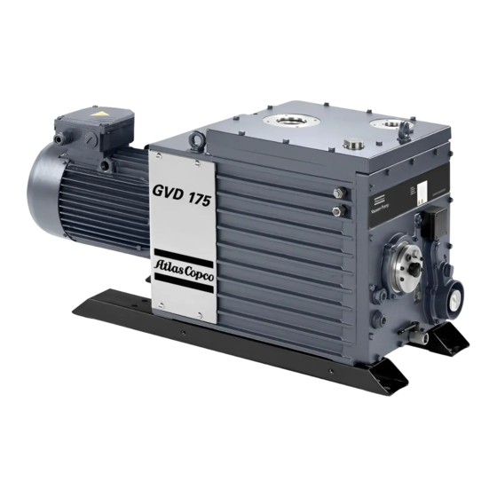
Page 8: The Gvd 175, Gvd 275 Pump
Instruction Book Figure 1 – The GVD 175, GVD 275 pump Reference Designation Reference Designation Gas-ballast control Oil-filter location Oil filler-plug Oil pressure-gauge Outlet-port Oil-level sight-glass Inlet-port Oil drain-tap Motor terminal-box (10) Cooling-water connections 6996 0220 90 Issue C... -
Page 9: Description
The GVD 175 and GVD 275 pumps are two-stage oil-sealed, high-vacuum pumps designed for reliable, long-term operation in both laboratory and industrial environments. A four-pole three-phase motor provides direct-drive through a flexible coupling. The pumps are free-standing mounted on steel runners. -
Page 10: Gas Ballast
1, item 1) open, when you switch the pump off, the pressure inside the pump will rise to atmospheric pressure. With the gas-ballast control closed, when you switch off the GVD 175 and GVD 275 pumps the vacuum will be maintained inside the pump. -
Page 11: Technical Data
Where total pressures are shown in the technical data tables, measurements were taken using an untrapped total pressure capacitance diaphragm gauge on a header, as specified by Pneurop standards. Parameter Units GVD 175 GVD 275 Maximum Displacement 50 Hz electrical supply 60 Hz electrical supply Maximum Speed –... -
Page 12: Dimensional Data
Instruction Book Figure 2 – Dimensions GVD 175, GVD 275 (mm) Dimensional data Dimensions (mm) Pump GVD 175 1011 1066 GVD 275 1152 1207 6996 0220 90 Issue C... -
Page 13: Mechanical Data
G1 1/2) Noise level at 1 metre (dB (A)) † Vibration Severity Class 1C for GVD 175 and Class 1D for GVD GVD 175 GVD 275 Maximum mass (kg) The noise level was measured in accordance with ISO2151 and with the pump running at ultimate pressure. -
Page 14: Lubrication Data
Instruction Book Lubrication data NOTE A Safety Data Sheet for the following oil is available on request. GVD 175 GVD 275 Recommended oil TIGOL 68 Oil capacity (litres) Maximum Minimum To operate your pump when the ambient temperature is outside the limits specified Section 2.1, or to optimise your pump performance when you pump condensable... -
Page 15: Installation
If you do, there is a risk of fire or explosion in the oil-box of the pump. WARNING We do not recommend that you use the GVD 175 and GVD 275 pumps to pump hazardous substances. You must ensure that the pump is suitable for your application. -
Page 16: Unpack And Inspect
Instruction Book If you use the pump in a high ambient temperature and have a high gas throughput, the temperature of the pump-body may exceed 70°C. You must fit suitable guards to prevent contact with hot surfaces. Make sure that the exhaust pipeline cannot become blocked. If you have an exhaust- ... -
Page 17: Connect The Pump To The Cooling Water
If you pump oxygen or other dangerous gases and vapours, you must use a chemically inert and stable oil (such as perfluoropolyether). For information on pumping dangerous gases and vapours, refer to the Atlas Copco guidelines on vacuum pump and vacuum system safety (see Associated Publications at the end of the contents list). -
Page 18: Electrical Installation
Instruction Book Figure 3 – Oil level indication 4. Refit the oil filler-plug. Tighten the plug firmly by hand. Do not over-tighten. Electrical installation 3.7.1 Connect the pump to your electrical supply WARNING Ensure that the electrical installation of your pump-motor conforms with your local and national safety requirements. -
Page 19: Connect The Pump Inlet To Your System
Instruction Book 1. Remove the cover from the motor terminal-box. 2. Check your electrical supply voltage and frequency. If necessary, configure the motor to operate with your electrical supply. For motor wiring information refer to the wiring diagram supplied in the motor terminal box. 3. -
Page 20: Connect The Pump Outlet To Your System
Instruction Book Take note of the following information when you connect the pump to your vacuum system. For optimum pumping speeds, ensure that the pipeline connected to the inlet-port is as short as possible and has an internal diameter not less than the inlet-port diameter. Support the vacuum pipelines to prevent loading of the coupling-joints. -
Page 21: Gas-Ballast Inlet Connection
Instruction Book 3.10 Gas-ballast inlet connection As shown in Figure 5 (item 3), the pump has two gas-ballast inlets. We supply the pump with a blanking plug fitted to one inlet: the other inlet is open. You can use either of the inlets, but you must fit the blanking plug to the inlet you do not use. -
Page 22: Operation
Instruction Book Operation Gas-ballast control Use the gas-ballast control (Figure 1, item 1) to change the amount of air introduced into the low-vacuum stage of the pump. Use of the gas-ballast will prevent the condensation of vapours in the pump. The condensed vapours would contaminate the oil. Turn the gas-ballast control fully clockwise: to achieve ultimate vacuum ... -
Page 23: To Achieve Ultimate Vacuum
Section 2, make sure that this is not due to your system design before you contact your supplier or Atlas Copco for advice. In particular, the vapour pressure of all materials used in your vacuum system, including pump oil, must be much lower than the specified ultimate vacuum of the pump. Refer to Section 5.12.2... -
Page 24: Unattended Operation
Instruction Book 3. Turn the gas-ballast control fully anti-clockwise. 4. Operate the pump until the oil is clear. Unattended operation The pump is designed for unattended operation under the normal operating conditions specified Section 2. However, we recommend that you check the pump at a regular interval of not more than 14 days. -
Page 25: Maintenance
Instruction Book Maintenance Refer to Section 5.2 recommended maintenance plan. Safety WARNING Obey the safety instructions given below and take note of appropriate precautions. If you do not, you can cause injury to people and damage to equipment. Ensure that maintenance is done by a suitably trained and supervised technician. Obey ... -
Page 26: Maintenance Plan
If necessary, adjust the maintenance plan according to your experience. When you maintain the pump, use Atlas Copco spares and maintenance kits; these contain all of the components necessary to complete maintenance operations successfully. The Item... -
Page 27: Replace The Oil
Instruction Book 3. If the oil is contaminated, drain and refill the pump with clean oil as described in Section 5.4. Replace the oil Refer to Figure 1 for the items in brackets. 1. Operate the pump for approximately ten minutes to warm the oil, then switch off the pump (this lowers the viscosity of the oil and enables it to be drained from the pump more easily). -
Page 28: Clean The Fine Oil-Filter
Instruction Book Clean the fine oil-filter Figure 4 – Remove and replace filter-element Reference Designation Reference Designation Pump end-plate Retaining screws Filter-adaptor assembly Filter head-plate gasket Filter head-plate Filter-element You must clean the fine oil-filter every time you change the oil in the pump. See Figure 1. -
Page 29: Replace The Gas-Ballast Filter
(2). 4. Withdraw the adjustor-knob bearing-plate from the pump end-plate (1). 5. Replace the felt filter-elements (6). There are two for GVD 175/275 pumps. Clean the assembly before re-fitting new filter-elements by washing in a suitable cleaning solution. Allow the assembly to dry. -
Page 30: Inspect And Clean The Inlet-Filter
Instruction Book Inspect and clean the inlet-filter You must remove and clean the inlet-filter (positioned in the inlet-port) every time you change the oil in the pump (see Figure Figure 6 – Remove and replace inlet-filter Reference Designation Inlet-filter Filter retainer-circlip 1. -
Page 31: Clean And Overhaul The Pump
Basic fault-finding A list of fault conditions and their possible causes is provided here to assist you in fault-finding. If you are unable to rectify a fault when you use this guide, call your nearest Atlas Copco Customer Centre for help. - Page 32 Instruction Book 5.12.2 The pump fails to achieve its specified performance (Failure to reach ultimate vacuum) The measuring technique or gauge is unsuitable You have filled the pump with the wrong type of oil There is a leak in your vacuum system ...
- Page 33 Instruction Book 5.12.5 The vacuum is not fully maintained after the pump is switched off The gas-ballast control is open Damaged or missing O-ring Anti-suckback valve faulty Shaft seals damaged Exhaust valve damaged 5.12.6 The pumping speed is poor The connecting pipelines are too small in diameter ...
-
Page 34: Storage And Disposal
Instruction Book Storage and disposal Storage CAUTION Observe the storage temperature limits stated in Section 2. Storage below -30°C will permanently damage the pump seals. NOTE If you will store a new pump in conditions of high humidity, remove the pump from its cardboard packaging box;... -
Page 35: Service, Spares And Accessories
Spares Refer to the corresponding Atlas Copco parts list. Accessories A range of accessories are available for the GVD 175 and GVD 275 pumps. 7.4.1 Outlet mist-filter The outlet mist-filter collects the oil contained in the oil-mist forming part of the discharge gases. - Page 36 This page has been intentionally left blank.
- Page 37 We make performance stand the test of time. This is what we call - Sustainable Productivity. Atlas Copco AB (publ) SE-105 23 Stockholm, Sweden Phone: +46 8 743 80 00 Reg. no: 556014-2720 www.atlascopco.com...
Need help?
Do you have a question about the GVD 175 and is the answer not in the manual?
Questions and answers