Table of Contents
Advertisement
Quick Links
Advertisement
Table of Contents

Related Manuals for OTT HydroMet SUTRON Compact Constant Flow Bubbler


Summary of Contents for OTT HydroMet SUTRON Compact Constant Flow Bubbler
- Page 1 Accubar / Compact Constant Flow Bubbler Operational Manual...
- Page 2 Sterling, VA 20164 +1 703 406-2800 sales@otthydromet.com www.otthydromet.com All rights reserved. All content is the intellectual property of OTT HydroMet. Reprinting, duplication and translation (even as excerpts) are only permitted with the prior written consent of OTT HydroMet. Subject to technical change.
-
Page 3: Table Of Contents
Table of contents Scope of supply Order numbers and variant code Product variants Accessories and spare parts About this manual Other applicable documents General signs and symbols Explanation of warnings General safety instructions Intended use Potential misuse Personnel qualification Operator obligations Personnel obligations Correct handling Risk of electrical shock... - Page 4 8.2.2 Power connection 8.2.3 SDI-12 connection Checking for blockage Commissioning Starting the device Operation 10.1 Front panel 10.1.1 Front panel key functions 10.1.2 Navigating the menu tree 10.1.3 Turning display on and off 10.1.4 Adjusting contrast 10.1.5 Viewing current data 10.1.6 Displaying errors 10.2 Settings...
- Page 5 Technical data 15.1 General technical data 15.2 Electrical data 15.3 Pneumatic data 15.4 Dimensions and weight 15.4.1 Constant Flow Bubbler, single orifice 15.4.2 Constant Flow Bubbler, dual orifice <5>...
-
Page 6: Scope Of Supply
1 Scope of supply The following items are included with delivery: – Constant Flow Bubbler (CFB) – 3/8" tube – Cover cap <6>... -
Page 7: Order Numbers And Variant Code
2 Order numbers and variant code 2.1 Product variants Constant Flow Bubbler, single orifice Variant Order number Accubar Constant Flow Bubbler 56-0133-25-1 Compact Constant Flow Bubbler with 3/8" fitting, 25 psi 56-0133-25-1S Compact Constant Flow Bubbler with 6 mm Fitting - Includes the desiccant 56-0133-25-1SC Compact Constant Flow Bubbler with 3/8"... -
Page 8: Accessories And Spare Parts
2.2 Accessories and spare parts Item Order number Platinum 385 water temperature sensor with cable (30 m/100 ft.) 5600-0100-100 Thermistor water temperature sensor with cable (15 m/50 ft) 5600-0030-1-050 Replacement desiccant, full canister 2911-1279-1 Orifice termination bubbler termination fits on a 50 mm/2” rigid pipe 6661-1314-1 Polyurethane, black orifice tubing - 9,5 mm/⅜”... -
Page 9: About This Manual
3 About this manual 3.1 Other applicable documents The following documents contain further information on installation, maintenance and calibration: – Operations & Maintenance Manual Accubar ® Constant Flow Bubble Gauge/Recorder 56-0133 and Dual Orifice Bubble Gauge/Recorder 56-0134. – Data Sheets –... -
Page 10: Explanation Of Warnings
3.3 Explanation of warnings To avoid personal injury and material damage, you must observe the safety information and warnings in the operating manual. The warnings use the following danger levels: WARNING WARNING This indicates a potentially hazardous situation. If the hazardous situation is not avoided, it may result in death or serious injuries. -
Page 11: General Safety Instructions
4 Do not change or convert the product in any way. 4 Do not perform any repairs yourself. 4 Get OTT HydroMet to examine and repair any defects. 4 Ensure that the product is correctly disposed of. Do not dispose of it in household waste. -
Page 12: Risk Of Electrical Shock
4.7 Risk of electrical shock Live parts can cause electric shocks in the event of contact. 4 Never touch live electrical parts. 4 Turn the power off or unplug before opening. 4.8 Certification CE (EU) The equipment meets the essential requirements of EMC Directive 2014/30/EU. FCC (US) FCC Part 15, Class "A"... -
Page 13: Product Description
5 Product description 5.1 Design and function The CFB is a self-contained, precision device for measuring water levels. The device combines a pump, tank, manifold, control board, front panel (display and keypad), Accubar sensor, SDI-12 and RS-232 interfaces, and enclosure for the purpose of measuring water levels using bubble gauge principles. The CFB with dual orifice is capable of providing redundant measurements, measuring water level in two separate bodies of water, accurately measuring water density, or providing an extended range of water level measurement. -
Page 14: Product Overview
5.2 Product overview 5.2.1 Enclosure Accubar CFB, single orifice Water temperature sensor connector Air outlet Terminal strip Breather vent DB9 connector Bulkhead fitting for external desiccant tube connection Compact CFB Water temperature sensor connector Breather vent Terminal strip Air outlet DB9 connector Bulkhead fitting for external desiccant tube connection... -
Page 15: Pneumatic Features
5.2.2 Pneumatic features Accubar CFB, single orifice Pump Vent valve Desiccant Manifold Accubar ® sensor Purge valve Relief valve <15>... - Page 16 Accubar CFB, dual orifice Tank 1 Vent valve 1 Pump Vent valve 2 Tank 2 Bypass line 2 Desiccant Bypass line 1 Accubar ® sensor 1 Tank valve Accubar ® sensor 2 <16>...
- Page 17 Compact CFB Pump Relief valve ® Accubar sensor Purge valve Desiccant Manifold Zero valve <17>...
-
Page 18: Transport, Storage, And Unpacking
6 Transport, storage, and unpacking 6.1 Transport 4 Transport the product always in its original packaging. 4 Ensure that the product is not mechanically stressed during transport. 6.2 Storage 4 Store within specified temperature ranges. 4 Store in dry area. 4 Store in original box where possible. -
Page 19: Quick Installation
7 Quick installation The device can be quickly installed and commissioned with the following steps. Additional settings can be made if required. Further information can be found in the Operations & Maintenance Manual Accubar ® Constant Flow Bubble Gauge/Recorder. 4 Mount the enclosure. See section Mounting enclosure [} 20] 4 Install the orifice lines in the desired locations. -
Page 20: Installation
8 Installation 8.1 Mechanical installation 8.1.1 Required tools and aids The following tools and aids are required: – Small flat blade screwdriver to tighten screws on terminal strip – Small Cross head (Phillips) screwdriver to mount terminal strip – Large Cross head (Phillips) screwdriver to mount mounting ears to enclosure –... -
Page 21: Electrical Installation
8.2 Electrical installation 8.2.1 Electrical connections 8.2.1.1 Terminal strip Pin number Assignment Comment Earth – DATA SDI-12 Not connected SDI-12 RS-485 A – RS-485 B – +12 V Power 12 V (4 amps) Power ground 8.2.1.2 DB9 connector The CFB comes with a DB9F connector for connection to RS-232 devices. The DB9F connector can be connected to the serial port on most PCs using a straight cable. -
Page 22: Power Connection
8.2.2 Power connection The device requires external +12 V power to operate. The most common power source for the device is a lead-acid battery. 4 Connect the battery or other high current source to pins 7 and 8 of the external terminal strip. 4 Use a wire that is at least 20 gauge and no longer than 1.5 m (5 ft.). -
Page 23: Commissioning
9 Commissioning 9.1 Starting the device The device starts operating as soon as power is applied. The display will turn on. If an Accubar sensor is installed, measurement will commence and the front panel will be updated with a water level reading. By default, the device will measure and log water level every 15 minutes;... -
Page 24: Operation
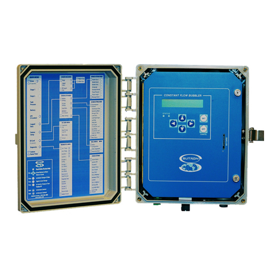
10 Operation 10.1 Front panel The front panel can be used to setup the station, examine it’s status, view the current measurements, and view logged data. Accubar CFB Swing out panel with menu tree SET and OFF key Desiccant view SD card slot LC-Display Status LED... -
Page 25: Front Panel Key Functions
10.1.1 Front panel key functions Symbol Meaning Function RIGHT navigates to a sub-menu (assuming there is one) LEFT goes back to the parent menu navigates among the menus on the same level 4 Hold UP to change contrast setting. DOWN navigates among the menus on the same level 4 Hold DOWN to change contrast setting. -
Page 26: Viewing Current Data
10.1.5 Viewing current data When the display is turned on, the last measured water level will display. The CFB will then initiate a new measurement and display the results as soon as the measurement completes (which is based on averaging time). As long as the water level menu is displayed, live readings will be continuously made. -
Page 27: Adjusting Bubble Rate
10.2.2 Adjusting bubble rate The bubble rate is the measure of the amount of air going down the orifice line per unit of time. The device supports two units for bubble rate: Bubbles per minute (BPM) and Standard Cubic Centimeters per Minute (SCCM). The bubble rate for a site with slowly changing levels is typically 60 bubbles per minute out of a 1/8 ID tube. -
Page 28: Setting Blockage Detection
10.2.5 Setting blockage detection The CFB automatically detects when the orifice line is blocked and intiates a purge. If the line is blocked, the pressure in the line increases and the sensors stop pumping in order not to overpressure. The automatic blockage detection prevents this. -
Page 29: Changing Automeasure Schedule
10.2.8 Changing automeasure schedule The device can measure and log water level data automatically. The interval and time for automeasure can be changed. Automeasure may not be turned off. 4 To change automeasure interval and time, use Station Setup > Accubar Setup at the front panel. In normal mode, data is measured and logged at the following times: Example 1: Automeasure time 00:00:00 interval 00:10:00 –... -
Page 30: Passive Sensor Mode
Example: Normal mode with 10 second averaging – 12:00:00 measure command is received (via SDI-12, front panel, RS232, or automeasure) – 12:00:00 sensors are powered on and measurement starts – 12:00:11 measurement completes with data collected between 12:00:00 and 12:00:10 –... - Page 31 FastTrackUp events. 4 To get diagnostics details about FastTrack, use Diagnostics at the front panel. The bubbler calls the pressure drop in the tube deltaP. 4 First consult OTT HydroMet before making any changes to the FastTrack settings. <31>...
-
Page 32: Maintenance
Annually 4 Have a calibration check performed. OTT HydroMet 11.2 Checking for leaks Leaks inside the device can be a source of inaccuracy or excessive pumping and use of desiccant. 4 To start the leak test, use Diagnostic > Leak Test at the front panel. -
Page 33: Conducting Purge
4 Press to got to Leak Test. 4 Press SET to conduct the leak test. 4 Press to view the results. ð When the leak test completes, the system displays a status indicating whether the device has passed or failed the leak test along with a score. -
Page 34: Replacing Desiccant
11.4 Replacing desiccant CAUTION Health hazard due to powdered desiccant! When the tube is opened, desiccant can escape and be inhaled or irritate the eyes. 4 Wear goggles and mask. 4 To disconnect the tube from the quick disconnect fitting, push the fitting collar around the tube flush against the fitting. - Page 35 4 Choose Y-Modem. 4 Select the upgrade file name stored on the computer. ð Once the download is completed, the system will reboot. 4 Type the command ‘Ver’ to confirm that the upgrade was successful. Using terminal emulator and ESCAPE key This method is used if a previous upgrade attempt was aborted, resulting in the device's main application not working.
-
Page 36: Troubleshooting
12 Troubleshooting 12.1 Error elimination Error Possible cause Corrective action Pressure dropping / excessive Leakage 4 Run leak test. pump operation 4 Observe error codes and refer to Hardware error codes [} 37]. Pressure dropping / excessive Orifice lines are not correctly 4 Ensure that the orifice lines are fully pump operation attached... -
Page 37: Hardware Error Codes
Error Possible cause Corrective action No data Command or address is wrongly 4 Ensure that the address is proper case written and that commands are written in upper case. All commands are capital letters. Garbled data Multiple sensors set to the same 4 Check address settings of all SDI sensors. - Page 38 Error code Description 4016 timeout emptying tank 4017 Accubar and tank sensor readings did not match 4018 restrictor not zero 4019 restrictor valve stuck open 4020 restrictor valve stuck closed 4021 restrictor pressure dropped too fast 4022 restrictor pressure dropped too slow 4023 line valve stuck open 4024...
-
Page 39: Repair
13 Repair 13.1 Customer support 4 Have repairs carried out by OTT HydroMet service personnel. 4 Only carry out repairs yourself, if you have first consulted OTT HydroMet. 4 Contact your local representative: www.otthydromet.com/en/contact-us 4 Include the following information: – instrument model –... -
Page 40: Notes On Disposing Of Old Devices
In accordance with the German Electrical and Electronic Equipment Act (ElektroG; national implementation of EU Directive 2012/19/EU), OTT HydroMet takes back old devices in the Member States of the European Union and disposes of them in the proper manner. The devices that this concerns are labeled with the following symbol: 4 For further information on the take-back procedure contact OTT HydroMet: OTT Hydromet Corp. -
Page 41: Technical Data
15 Technical data 15.1 General technical data Specification Value Operating temperature range Standard -25 to +60 °C (-13 to +140 °F) Optional -40 to +60 °C (-40 to +140 °F) Operating humidity 0 to 95 % (non-condensing) Water temperature: Types supported Platinum 385, Platinum 392, Thermistor, Custom Sensor operational range -40 to +60 °C (-40 to +140 °F) Accuracy* ±0.1 °C (-5 to +45 °C) Resolution* 0.01 °C Suspended sediment:... -
Page 42: Pneumatic Data
15.3 Pneumatic data Specification Value Pressure range* 25 psi device 0 to 17.5 m (0 to 57.5 ft) 50 psi device 0 to 35 m (0 to 115 ft) Accuracy* 0 to 6 m (0 to 20 ft): ±0.00305 m (±0.01 ft) 25 psi device 6 to 17,5 m (20 to 57,5 ft): ±0.05 % reading 50 psi device 17,5 to 35 m (57,5 to 115 ft): ±0.05 % reading Resolution... -
Page 43: Constant Flow Bubbler, Dual Orifice
15.4.2 Constant Flow Bubbler, dual orifice 275 mm 323 mm Accubar CFB Specification Value Dimensions packed (h x l x w) 510 x 381 x 254 mm (20 x 15 x 10 in) Dimensions unpacked (h x l x w) 373 x 323 x 191 mm (15 x 13 x 7.5 in) Weight unpacked 9.1 kg (20 lbs.) Weight packed 10 kg (22 lbs.) <43>... - Page 44 Contact Information...
Need help?
Do you have a question about the SUTRON Compact Constant Flow Bubbler and is the answer not in the manual?
Questions and answers