Table of Contents
Advertisement
Quick Links
Advertisement
Table of Contents

Related Manuals for OTT HydroMet KIPP & ZONEN SMP Series


Summary of Contents for OTT HydroMet KIPP & ZONEN SMP Series
- Page 1 OTT HydroMet brand SMP Series Smart Pyranometers Operational Manual...
- Page 2 2628 XH Delft The Netherlands +31 15 2755 210 solar-info@otthydromet.com www.otthydromet.com All rights reserved. All content is the intellectual property of OTT HydroMet. Reprinting, duplication and translation (even as excerpts) are only permitted with the prior written consent of OTT HydroMet. Subject to technical change.
-
Page 3: Table Of Contents
Table of contents Scope of supply Order numbers and variant code Product variants Accessories and spare parts About this manual Other applicable documents General signs and symbols Explanation of warnings General safety instructions Intended use Potential misuse Personnel qualification Personnel obligations Danger of burns due to hot surfaces Correct handling Certification... - Page 4 7.3.4 Power consumption 7.3.5 Analog voltage output 7.3.6 Analog current output 7.3.7 Connecting to computer Commissioning Set up instrument 8.1.1 Starting the Smart Explorer Software 8.1.2 Establishing connections 8.1.3 Adjusting the communication parameters 8.1.4 Finding an instrument with unknown communication parameters Operation Making and saving measurements Collecting data...
-
Page 5: Scope Of Supply
1 Scope of supply The following items are included with SMP series pyranometers: – Smart pyranometer – Sun shield – Optional cable, pre-wired with 8-pins connector or connector only for customer cable – Calibration certificate – Instruction sheet – Pyranometer fixing kit SMP3: –... -
Page 6: Order Numbers And Variant Code
2 Order numbers and variant code 2.1 Product variants Variant Order number SMP3 0374900 SMP6 0374920 SMP10 0374905 SMP22 0374940 2.2 Accessories and spare parts Accessories Item Order number CVF 4 Ventilation Unit 0378910 CMF1 - Albedometer mount 0362700 CMF4 - Albedometer mount 0362703 Unventilated glare screen kit 0305722... -
Page 7: About This Manual
3 About this manual 3.1 Other applicable documents The following documents contain further information on installation, maintenance and calibration: – Smart Pyranometer Communication Manual – Smart Explorer Software Manual 3.2 General signs and symbols The signs and symbols used in the operating manual have the following meaning: Practical tip This symbol indicates important and useful information. -
Page 8: General Safety Instructions
4 Do not change or convert the product in any way. 4 Do not perform any repairs yourself. 4 Get OTT HydroMet to examine and repair any defects. 4 Ensure that the product is correctly disposed of. Do not dispose of it in household waste. -
Page 9: Certification
4.7 Certification CE (EU) The equipment meets the essential requirements of EMC Directive 2014/30/EU. FCC (US) FCC Part 15, Class "B" Limits This device complies with part 15 of the FCC Rules. Operation is subject to the following two conditions: 1. -
Page 10: Product Description
5 Product description 5.1 Design and function The SMP series instruments are radiometers designed for measuring short-wave irradiance on a plane surface (radiant flux, W/m ) which results from the sum of the direct solar radiation and the diffuse sky radiation incident from the hemisphere above the instrument. -
Page 11: Product Overview
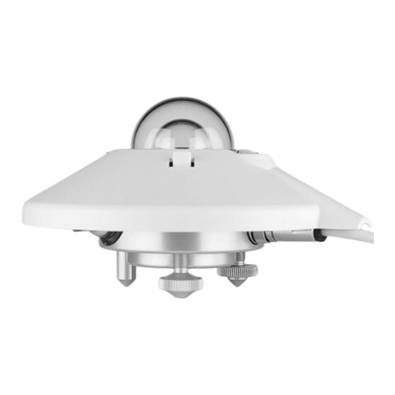
5.2 Product overview SMP3 pyranometer Sun shield Adjustable leveling feet Thermopile detector Smart interface Glass dome Fixed foot Connector Housing Bubble level SMP6, SMP10, SMP22 pyranometers Sun shield Housing Inner glass dome Adjustable leveling feet Outer glass dome Smart interface Thermopile detector Fixed foot Bubble level... -
Page 12: Transport, Storage, And Unpacking
6 Transport, storage, and unpacking 6.1 Unpacking 4 Carefully remove the product from the packaging. 4 Check that the delivery is complete and undamaged. 4 If you find any damage or if the delivery is incomplete, then immediately contact the supplier and manufacturer. -
Page 13: Installation
7 Installation 7.1 Planning installation For the solar irradiation to be measured in the entire photovoltaic system, it is necessary to position several pyranometers in the system. The number of pyranometers required depends on the system’s performance and ambient conditions. The minimum number of sensors required for a Class A system is defined as follows: –... - Page 14 The 5 degrees correspond to a minimum distance from the instrument to the obstacle of 10 times the height of the obstacle: >10 x h Minimum distance from instrument to obstacle The minimum distance is important for measuring the direct radiation. The diffuse solar radiation is not so affected by obstacles near the horizon.
-
Page 15: Installation For Measuring Global Radiation On Sloping Surfaces
4 Position the instrument in such a way that the nuts are located at a distance of 2 to 3 mm from the mounting device. 4 Ensure that the instrument is grounded. 4 Ensure that the instrument is not in the shade. 4 When installed horizontally, point the cable connector towards the nearest pole to reduce the UV exposure on the cable. -
Page 16: Installation For Measuring Reflected Radiation
7.2.5 Installation for measuring reflected radiation In inverted position the pyranometer measures the reflected global radiation. Mounting plate Pyranometer Glare screen Mast Equator The mounting plate prevents the pyranometer from being heated by solar radiation. The optional glare screen has an angle of 5 degrees and prevents direct radiation on the glass dome during sunrise and sunset. -
Page 17: Installation For Measuring Diffuse Radiation
7.2.7 Installation for measuring diffuse radiation For the diffuse radiation to be measured, the direct radiation on the pyranometer’s glass dome must be blocked. The direct radiation can be blocked using a static shadow ring or a two-axis automatic sun tracker. Shadow ring Pyranometer Mounting bracket... -
Page 18: Electrical Installation
7.3 Electrical installation 7.3.1 Electrical connections SMP pyranometers are supplied with a waterproof connector pre-wired to 10 m of high quality yellow cable with 8 wires and a shield covered with a black sleeve. Long cables may be used if the cable resistance is less than 0.1 % of the impedance of the readout equipment for the analog outputs. -
Page 19: Analog Voltage Output
Typical power consumption SMP-A for max output (20 mA) Voltage on the pyranometer (V DC) Current (mA with 100 Ω load Power (mW) resistor) The above Megawatt values represent the dissipation within the SMP-A. For the total power the energy in the load resistor has to be added. -
Page 20: Connecting To Computer
7.3.7 Connecting to computer NOTICE Damage due to lack of insulation! The power supply units of portable computers such as laptops can generate large voltage peaks. This may cause damage to the instrument’s digital interface. 4 Ensure that the converter has galvanic separation between the inputs and outputs. The instrument must be connected to a computer via an RS-485 converter with a USB port. -
Page 21: Commissioning
8 Commissioning 8.1 Set up instrument The Smart Explorer software allows to configure a smart sensor and to collect real-time data. The factory default communication parameters are as follows: – Modbus ® baud rate: 19200 – Parity: even – Data bits: 8 –... -
Page 22: Starting The Smart Explorer Software
8.1.1 Starting the Smart Explorer Software 4 Start the Smart Explorer Software: 4 Click on the Setup menu and check whether the following settings are activated: 4 Adjust the settings if necessary. 4 Click on the Update button to save the settings. <22>... -
Page 23: Establishing Connections
8.1.2 Establishing connections 4 To establish a connection to the instrument, click on the Setup Connection button. 4 Activate the Serial RTU protocol to establish the direct RS-485 connection. 4 Select the COM port (see Windows Device Manager). 4 Leave the other factory settings unchanged. 4 Click on the Confirm button to save the settings. -
Page 24: Adjusting The Communication Parameters
8.1.3 Adjusting the communication parameters 4 Click on the Configuration tab to access the current communication parameters. 4 To change the parameters, click on the Configure Device button. ð The following warning appears: <24>... - Page 25 4 To change the Modbus address, the baud rate and the parity, close the window and activate the Single Instrument Use operating mode on the Connections tab. The Modbus address can also be changed in the Normal Network Use operating mode. 4 Go to the Configuration tab and click on the Configure Device button again.
-
Page 26: Finding An Instrument With Unknown Communication Parameters
8.1.4 Finding an instrument with unknown communication parameters 4 Activate the Single Instrument Use operating mode on the Connections tab. 4 If only the Modbus address is unknown, click on the Send Broadcast button. ð The connected pyranometer is displayed: 4 If no instrument is found, click on the Start From Boot button. -
Page 27: Operation
9 Operation 9.1 Making and saving measurements The instruments require suitable sources of power and radiation (light) to operate and make measurements. 4 To save the measurements, connect the instrument to a readout or data storage device. The instrument has no internal data memory. -
Page 28: Maintenance
4 Check all cables for damage. 4 Check fastenings and basic supports. 4 Clean the sun shield if dirty. 2 years 4 Check sensitivity or have a recalibration performed. OTT HydroMet 10 years 4 Replace the desiccant in the pyranometer. OTT HydroMet <28>... -
Page 29: Troubleshooting
4 For analog outputs, check the data logger or integrator input offset so that a signal of 0 V or 4 mA gives a "zero" reading. 4 Check that the leveling is correct. 4 Report any malfunctions or damage to the representative of OTT HydroMet. <29>... -
Page 30: Repair
12 Repair 12.1 Customer support 4 Have repairs carried out by OTT HydroMet service personnel. 4 Only carry out repairs yourself if you have first consulted OTT HydroMet. 4 Contact your local representative: www.otthydromet.com/en/contact-us 4 Include the following information: – instrument model –... -
Page 31: Notes On Disposing Of Old Devices
In accordance with the German Electrical and Electronic Equipment Act (ElektroG; national implementation of EU Directive 2012/19/EU), OTT HydroMet takes back old devices in the Member States of the European Union and disposes of them in the proper manner. The devices that this concerns are labeled with the following symbol: 4 For further information on the take-back procedure contact OTT HydroMet: OTT HydroMet B.V. -
Page 32: Technical Data
14 Technical data 14.1 Optical and electrical data Specification SMP3 SMP6 SMP10 SMP22 Classification to Spectrally flat Class C Spectrally Flat Class B Spectrally Flat Class A Spectrally Flat Class A ISO 9060:2018 Analog output , V-version 0 to 1 V 0 to 1 V 0 to 1 V 0 to 1 V Analog output range, V-version -200 to 2000 W/m -200 to 2000 W/m... - Page 33 Specification SMP3 SMP6 SMP10 SMP22 Directional response < 20 W/m < 15 W/m < 10 W/m < 5 W/m (up to 80° with 1000 W/m beam) Temperature response < 3 % < 2 % < 1 % < 0.3 % (-20 °C to +50 °C) (-10 °C to +40 °C) (-20 °C to +50 °C) (-20 °C to +50 °C) < 4 % < 4 % < 2 % < 0.3 % (-40 °C to +70 (-40 °C to +70 (-40 °C to +70 (-40 °C to +70...
- Page 34 Specification SMP3 SMP6 SMP10 SMP22 Recommended applications Economical solution for Good quality measurements for High performance for PV panel Scientific research requiring the efficiency and maintenance Solar Monitoring, hydrology and thermal collector testing, highest level of measurement monitoring of PV power networks, greenhouse climate solar energy research, solar accuracy and reliability under...
-
Page 35: Dimensions And Weight
14.2 Dimensions and weight 50 mm 32 mm 110 mm 150 mm 167 mm SMP3 SMP6, SMP10, SMP22 Specification SMP3 SMP6, SMP10, SMP22 Instrument weight 300 g 600 g Dimensions unpacked (diameter x height) 11 x 8.4 cm 15 x 9.3 cm Packaging dimensions 29 x 21 x 10 cm 22,5 x 19 x 15 cm Weight of 10 m cable 400 g <35>... - Page 36 Contact Information...
Need help?
Do you have a question about the KIPP & ZONEN SMP Series and is the answer not in the manual?
Questions and answers