
Related Manuals for OTT HydroMet KIPP & ZONEN SUV Series


Summary of Contents for OTT HydroMet KIPP & ZONEN SUV Series
- Page 1 OTT HydroMet brand CUV5 and SUV Series Ultraviolet Radiometers Operational Manual...
- Page 2 2628 XH Delft The Netherlands +31 15 2755 210 solar-info@otthydromet.com www.otthydromet.com All rights reserved. All content is the intellectual property of OTT HydroMet. Reprinting, duplication and translation (even as excerpts) are only permitted with the prior written consent of OTT HydroMet. Subject to technical change.
-
Page 3: Table Of Contents
Table of contents Scope of supply Order numbers and variant code Product variants Accessories and spare parts 2.2.1 Accessories 2.2.2 Cables and plugs About this manual Other applicable documents General signs and symbols Explanation of warnings General safety instructions Intended use Potential misuse Personnel qualification Personnel obligations... - Page 4 Set up instrument 8.1.1 Starting the Smart Explorer Software 8.1.2 Establishing connections 8.1.3 Adjusting the communication parameters 8.1.4 Finding an instrument with unknown communication parameters Operation Making and saving measurements Collecting data Maintenance 10.1 Maintenance schedule 10.2 Replacing desiccant Troubleshooting 11.1 Fault elimination Repair...
-
Page 5: Scope Of Supply
1 Scope of supply The following items are included with the radiometers: – UV Radiometer – Sun shield – Cable and plug – Calibration certificate – Instruction sheet – Fixing kit: – 2 stainless steel screws M5 x 80 mm – Nuts and flat washers –... -
Page 6: Order Numbers And Variant Code
2 Order numbers and variant code 2.1 Product variants Variant Order number CUV5 0364910 SUV5 0377900 SUV-A 0387910 SUV-B 0387920 SUV-E 0387930 2.2 Accessories and spare parts 2.2.1 Accessories For CUV5, SUV-A, SUV-B, SUV-E Item Order number CVF 4 Ventilation Unit 0378910 CMF1 - Albedometer mount 0362700... -
Page 7: Cables And Plugs
2.2.2 Cables and plugs For CUV5 Item Order number Waterproof 2-pin plug 2523144 10 m cable, pre-wired with waterproof 2-pin plug 0362601 25 m cable, pre-wired with waterproof 2-pin plug 0362603 50 m cable, pre-wired with waterproof 2-pin plug 0362604 100 m cable, pre-wired with waterproof 2-pin plug 0362605 For SUV5, SUV-A, SUV-B, SUV-E Item... -
Page 8: About This Manual
3 About this manual 3.1 Other applicable documents The following documents contain further information on installation, maintenance and calibration: – Smart Pyranometer Communication Manual – Smart Explorer Software Manual 3.2 General signs and symbols The signs and symbols used in the operating manual have the following meaning: Practical tip This symbol indicates important and useful information. -
Page 9: General Safety Instructions
4 Do not change or convert the product in any way. 4 Do not perform any repairs yourself. 4 Get OTT HydroMet to examine and repair any defects. 4 Ensure that the product is correctly disposed of. Do not dispose of it in household waste. -
Page 10: Certification
4.7 Certification CE (EU) The equipment meets the essential requirements of EMC Directive 2014/30/EU. FCC (US) FCC Part 15, Class "B" Limits This device complies with part 15 of the FCC Rules. Operation is subject to the following two conditions: 1. -
Page 11: Product Description
5 Product description 5.1 Design and function CUV5 and SUV radiometers are designed and calibrated to measure global ultraviolet (UV) solar irradiance. There are models for the specific UV bands and they provide measurements in units of W/m – CUV5 and SUV5 cover the total UV range. –... -
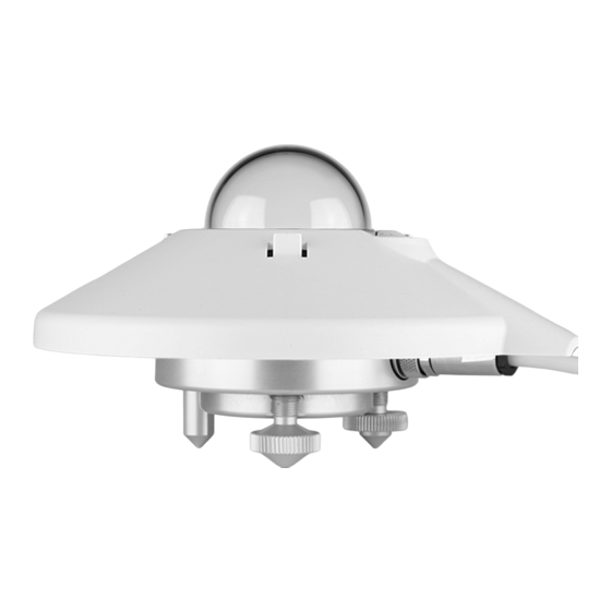
Page 12: Product Overview
5.2 Product overview CUV5 radiometer Sun shield Connector Diffusor Housing Glass dome Adjustable leveling feet Photodiode detector Fixed foot Bubble level Drying cartridge SUV radiometers Sun shield Housing Diffusor Adjustable leveling feet Glass or quartz dome Smart interface Photodiode detector Fixed foot Bubble level Internal desiccant... -
Page 13: Transport, Storage, And Unpacking
6 Transport, storage, and unpacking 6.1 Unpacking 4 Carefully remove the product from the packaging. 4 Check that the delivery is complete and undamaged. 4 If you find any damage or if the delivery is incomplete, then immediately contact the supplier and manufacturer. -
Page 14: Installation
7 Installation 7.1 Mechanical installation 7.1.1 Preparatory work 4 Check the desiccant of the CUV5 radiometer and replace the desiccant if necessary. 4 If using the digital output of the SUV radiometer, set the Modbus ® address before visiting the site. Otherwise a computer and RS-485 / USB converter is required during installation. - Page 15 7.1.3.2 Mounting 65 mm 2x M5 x 80 mm screws 2x flat washers 2x nylon insulating rings 2x nuts 2x Ø 5.2 mm 4 To insulate the instrument against the temperature of the mounting device, place the instrument on the adjustable foot and the two leveling feet. 4 Position the instrument in such a way that the nuts are located at a distance of 2 to 3 mm from the mounting device.
-
Page 16: Electrical Installation
7.2 Electrical installation 7.2.1 Electrical connections of CUV5 radiometer NOTICE Damage due to power supply! The instrument does not require power. Connecting power causes damage to the instrument. 4 Do not connect the instrument to power supply. The CUV5 radiometer has a 2-wire cable and 2-pin connector. The maximum recommended cable length is 100 m of good quality shielded 2-core signal cable. -
Page 17: Grounding Radiometer
7.2.2.3 Connecting to computer NOTICE Damage due to lack of insulation! The power supply units of portable computers such as laptops can generate large voltage peaks. This may cause damage to the instrument’s digital interface. 4 Ensure that the converter has galvanic separation between the inputs and outputs. The instrument must be connected to a computer via an RS-485 converter with a USB port. -
Page 18: Analog Voltage Output
7.2.4 Analog voltage output CUV5 radiometer The analog voltage output is generated directly by the photodiode detector in response to received radiation. The individual sensitivity is used to convert the output signal in in μV to W/m of irradiance when recorded by a data logger. -
Page 19: Commissioning
8 Commissioning 8.1 Set up instrument The Smart Explorer software allows to configure a smart sensor and to collect real-time data. The factory default communication parameters are as follows: – Modbus ® baud rate: 19200 – Parity: even – Data bits: 8 –... -
Page 20: Starting The Smart Explorer Software
8.1.1 Starting the Smart Explorer Software 4 Start the Smart Explorer Software: 4 Click on the Setup menu and check whether the following settings are activated: 4 Adjust the settings if necessary. 4 Click on the Update button to save the settings. <20>... -
Page 21: Establishing Connections
8.1.2 Establishing connections 4 To establish a connection to the instrument, click on the Setup Connection button. 4 Activate the Serial RTU protocol to establish the direct RS-485 connection. 4 Select the COM port (see Windows Device Manager). 4 Leave the other factory settings unchanged. 4 Click on the Confirm button to save the settings. -
Page 22: Adjusting The Communication Parameters
8.1.3 Adjusting the communication parameters 4 Click on the Configuration tab to access the current communication parameters. 4 To change the parameters, click on the Configure Device button. ð The following warning appears: <22>... - Page 23 4 To change the Modbus address, the baud rate and the parity, close the window and activate the Single Instrument Use operating mode on the Connections tab. The Modbus address can also be changed in the Normal Network Use operating mode. 4 Go to the Configuration tab and click on the Configure Device button again.
-
Page 24: Finding An Instrument With Unknown Communication Parameters
8.1.4 Finding an instrument with unknown communication parameters 4 Activate the Single Instrument Use operating mode on the Connections tab. 4 If only the Modbus address is unknown, click on the Send Broadcast button. ð The connected pyranometer is displayed: 4 If no instrument is found, click on the Start From Boot button. -
Page 25: Operation
9 Operation 9.1 Making and saving measurements The instruments require suitable sources of power and radiation (light) to operate and make measurements. 4 To save the measurements, connect the instrument to a readout or data storage device. The instrument has no internal data memory. -
Page 26: Maintenance
4 Check fastenings and basic supports. 4 Clean the sun shield if dirty. 2 years 4 Check sensitivity or have a recalibration performed. OTT HydroMet 10 years 4 Replace the desiccant in the SUV radiometers. OTT HydroMet 10.2 Replacing desiccant The SUV radiometers have an internal desiccant that need replacement after 10 years. -
Page 27: Troubleshooting
4 For analog outputs, check the data logger input offset so that a signal of 0 V gives a "zero" reading. 4 Check that the leveling is correct. 4 Report any malfunctions or damage to the representative of OTT HydroMet. <27>... -
Page 28: Repair
12 Repair 12.1 Customer support 4 Have repairs carried out by OTT HydroMet service personnel. 4 Only carry out repairs yourself if you have first consulted OTT HydroMet. 4 Contact your local representative: www.otthydromet.com/en/contact-us 4 Include the following information: – instrument model –... -
Page 29: Notes On Disposing Of Old Devices
In accordance with the German Electrical and Electronic Equipment Act (ElektroG; national implementation of EU Directive 2012/19/EU), OTT HydroMet takes back old devices in the Member States of the European Union and disposes of them in the proper manner. The devices that this concerns are labeled with the following symbol: 4 For further information on the take-back procedure contact OTT HydroMet: OTT HydroMet B.V. -
Page 30: Technical Data
14 Technical data 14.1 Optical and electrical data Specification CUV5 SUV5 SUV-A SUV-B SUV-E Spectral range (overall) 280 to 400 nm 280 to 400 nm 315 to 400 nm 280 to 315 nm 280 to 400 nm according to ISO/IEC 17166:2019 Measurement range 0 to 100 W/m 0 to 400 W/m 0 to 90 W/m 0 to 9 W/m... - Page 31 Specification CUV5 SUV5 SUV-A SUV-B SUV-E Storage temperature -40 °C to +80 °C -40 °C to +80 °C -40 °C to +80 °C -40 °C to +80 °C -40 °C to +80 °C range Humidity range 0 to 100 % 0 to 100 % 0 to 100 % 0 to 100 % 0 to 100 % Ingress Protection (IP) rating Analog output...
-
Page 32: Dimensions And Weight
14.2 Dimensions and weight 50 mm 150 mm 167 mm SMP6, SMP10, SMP22 Specification CUV5 SUV5, SUV-A, SUV-B, SUV-E Instrument weight 600 g 600 g Dimensions unpacked (diameter x height) 15 x 9.3 cm 15 x 9.3 cm Packaging dimensions 23 x 20 x 16 cm 23 x 20 x 16 cm Weight of 10 m cable 400 g <32>... -
Page 33: Appendix
15 Appendix 15.1 UV broadband radiometers CUV5 and SUV radiometers are designed for continuous outdoor use in routine monitoring applications with the sun as the source. However, they can also be used in indoors in test chambers and laboratories; bearing in mind the specifications of the UV source (lamp) and of the radiometer used. - Page 34 However, when the received solar spectrum changes due to atmospheric conditions, or when a different light source such as a lamp is used, the ratio between the instrument’s enclosed irradiance and the ideal enclosed irradiance can vary and "spectral errors" will occur. The figure below shows the ideal spectral response for "total UV"...
- Page 35 The next figure shows the "enclosed radiation”. This is per wavelength the product of the instrument’s response and the irradiance level at that wavelength. The instrument’s detector signal represents the enclosed radiation; the sum over the whole range of wavelengths, represented by the area under the curve (the integral). Enclosed irradiance for ideal response and CUV5 response Wavelength [nm] The enclosed radiation of the G 173 spectrum as measured by the CUV/SUV5 (light gray solid line)
-
Page 36: Indoor Measurement With Lamps
Typical spectral errors that can occur for solar irradiance measurement due to spectral changes over solar zenith angles 0° – 70° and total ozone columns 260 – 400 DU are shown in the following table: CUV5 and SUV5 SUV-A SUV-B SUV-E +2 % +2 % +5 % +2 % -2 % -2 % -15 %... - Page 37 To ensure the response at 90° angle of incidence is zero (cos. 90° = 0) a rim shades the diffuser side at SZA >85°. The shape of the diffuser ensures a good cosine response. Due to tolerances of the components and in assembly, there is a slight variation in directional response between radiometers.
- Page 38 <38>...
- Page 39 <39>...
- Page 40 Contact Information...
Need help?
Do you have a question about the KIPP & ZONEN SUV Series and is the answer not in the manual?
Questions and answers