Table of Contents
Advertisement
Quick Links
Advertisement
Table of Contents

Subscribe to Our Youtube Channel
Related Manuals for OTT HydroMet KIPP & ZONEN SMP12


Summary of Contents for OTT HydroMet KIPP & ZONEN SMP12
- Page 1 Instruction Manual SMP12 • Smart Pyranometer Confidential - Company Proprietary...
-
Page 2: Important User Information
Warranty and Liability OTT HydroMet B.V. guarantees that the product delivered under the Kipp & Zonen brand name has been thoroughly tested to ensure that it meets its published specifications. The warranty included in the conditions of delivery is valid only if the product has been installed and used according to the instructions supplied by OTT HydroMet B.V. -
Page 3: Table Of Contents
Table of Contents Contents Important user information .............................. 2 Introduction ..................................6 Safety precautions ..............................6 Waste disposal- WEEE directive 2012/19/EU......................6 Product overview ................................7 The SMP12 pyranometer ............................7 Included with the product ............................. 8 Intended use ................................8 International Standards ............................ - Page 4 Location ................................24 Mounting ................................. 24 Horizontal orientation ............................ 25 Horizontal levelling of the instrument ......................25 Fitting the connector and cable ........................26 Fitting the sun shield ............................26 Installation for measurement of tilted (POA) global irradiance ................. 27 Tilted installation of the instrument ......................
- Page 5 Read-write Holding registers ..........................46 Holding register details ............................46 Copyright notices ..............................48 Using this table Click on any item in the table of contents to be taken directly to the relevant page. Click on the bottom of any page to be taken back to the table of contents. Confidential - Company Proprietary...
-
Page 6: Introduction
Introduction Reading this entire manual is recommended for a full understanding of this product. CAUTION The triangle with exclamation mark is intended to alert the user to the presence of important installation, operating and maintenance instructions in the literature accompanying the instrument. WARNING Low voltage electrical equipment This low voltage electrical equipment should only be installed and serviced by authorized personnel, meaning people who have been trained and designated as “authorized”... -
Page 7: Product Overview
This manual, together with the instruction sheet, and the Smart Explorer manual, provides information related to the installation, maintenance, calibration, product specifications and applications of the SMP12 pyranometer. If any questions should remain, please contact your local OTT HydroMet representative or e-mail the Kipp & Zonen customer and product support department at: solar-support@otthydromet.com. Please go to www.kippzonen.com... -
Page 8: Included With The Product
Included with the product The following items are included with the SMP12 pyranometer: SMP12 Smart Pyranometer Sun shield Optional cable 10, 25, 50, 100m pre-wired with 8-pins connector and connector-only available for customer to build their own cable ISO 9060:2018 compliant calibration, directional response and temperature dependency certificate Instruction sheet Smart pyranometer fixing kit;... -
Page 9: Operation, Measurement And Background
Operation, measurement and background The SMP12 only requires a suitable source of power and radiation (light) to operate and make measurements. However, it is necessary to connect them to some sort of readout or data storage device in order to save the measurements, as there is no internal data memory. -
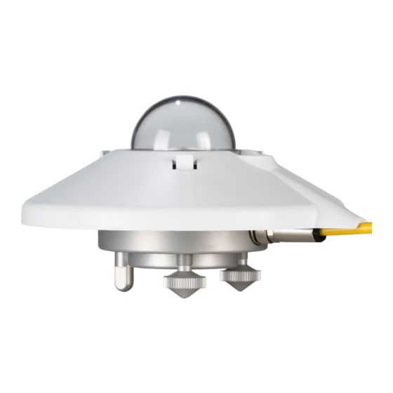
Page 10: Key Parts Of The Smp12 Pyranometer
Key parts of the SMP12 pyranometer The detector of the SMP12 is based on a passive thermal sensing element called a thermopile. Although the detector construction differs between models, the fundamental working principle is applicable to all SMP pyranometers. The thermopile responds to the total incoming energy through the diffuser, which is non-spectrally selective. The thermopile warms up and the heat generated flows through a thermal resistance to a heat-sink, the pyranometer housing. -
Page 11: Housing
For the SMP12 this desiccant is internal and lasts for 10 years. The desiccant will be exchanged when the instrument in returned to an OTT HydroMet (approved) service location for re-calibration. -
Page 12: Specifications
Specifications OTT HydroMet reserves the right to make changes to specifications and other product documentation without prior notice. Optical and electrical ISO 9060:2018 Fast Response Spectrally Flat Class A IEC 61724-1:2021 Class A Serial output RS-485 Modbus® RTU 2-wire, adjustable with Smart Explorer Software Serial output range -200 to 2000 W/m²... -
Page 13: Dimensions And Weight
Dimensions and weight 22.5 x 19.0 x 15.0 cm Dimensions packed 15 cm x 9.3 cm Dimensions unpacked 1250 g Weight packed with 10m cable 850 g Weight packed without cable Weight SMP12 unpacked 500 g Weight 10m cable unpacked 400 g Confidential - Company Proprietary... -
Page 14: Planning The Installation Of The Smp12
Planning the installation of the SMP12 This chapter describes the best locations to place the SMP12. Where to place SMP12 in the PV plant For getting a good representation of solar irradiance across the PV plant, one should place multiple SMP12s across the plant. -
Page 15: Installation
Installation Please follow the instructions in this section carefully for the mechanical and electrical installation of the SMP series pyranometers. Do not turn on power to the instrument, Do not connect the instrument to a computer, until instructed to. Tools required On-site: The tools required to fit an SMP12 pyranometer to a support are an 8mm flat hat slotted screwdriver and a 8 mm wrench / spanner. -
Page 16: Pre-Check
Pre-check Check the contents of the shipment for completeness (see section 3.2) and note whether any damage has occurred during transport. If there is damage, a claim should be filed with the carrier immediately. In the case of damage and/or the contents are incomplete, contact your local representative or e-mail the customer and product support department at: solar-support@otthydromet.com Please keep the original packaging for safe transport to the measurement site, or for use when returning for calibration. - Page 17 When using an industry standard USB-RS485 converter the following connections need to be made. Red and White wires must be connected together at the power supply and Brown and Black must be connected together at the power supply. This is to minimize voltage drop over the cable. (see paragraph 6.2 for details) Note : The blue RS-485 ground and both brown and black power grounds are interconnected in the SMP12.
-
Page 18: Changing The Settings Of The Smp12
Changing the settings of the SMP12 For changing the SMP12 settings the Smart Explorer software is needed as well as a connected and powered SMP12. The software and its manual are downloadable from the download center on www.kippzonen.com. Finding the COM port for the USB-RS-485 converter After starting the Smart Explorer software the user needs to select the right COM port on which your USB-RS-485 converter has been installed by the Windows®... -
Page 19: Configuring The Settings
Configuring the settings In order to connect to the SMP12: click on “Setup Connection” Select “Serial RTU protocol” for the direct RS485 connection that you’re using. Select the “COM port” you found in the Windows Device Manager. Leave the other settings unchanged as these are the factory defaults for all Kipp & Zonen products. Note : If you have changed the communication settings of the pyranometer and returned to the Smart Explorer then you have to change the settings to match to pyranometer. -
Page 20: Main Window - Configuration And Changes To It
Main window – Configuration and changes to it Clicking the “Configuration” tab shows the current communications settings. To change the SMP12 settings. Click on and a warning is shown. Read carefully. Confidential - Company Proprietary... -
Page 21: Finding A Smp12 With Unknown Communication Parameters
Go back to the first Connections tab to change to “Single Instrument Use” when the baud rate or parity needs to be changed too. Modbus address changes work also in Normal Network Use. For changing just the Modbus address select “Change Modbus Address” and select the new Modbus address. followed by Next and Update on the next screen. - Page 22 First change to “Single Instrument Use” in the “Connections” tab When the communication parameters are known and properly setup and only the Modbus ID is unknown a Send Broadcast will find the attached SMP12 and show it. If no instrument is found then mostlikely also one of the communication parameters is different or unknown. To always find an SMP12, there is the “Start From Boot”...
- Page 23 After a “Start From Boot” the instrument uses temporary settings and a 10 second power off is needed to get it to use the power on settings again. All other functionality of the Smart Explorer software is explained in the Smart Explorer manual, downloadable from the Kipp &...
-
Page 24: Proper Installation For Measurement Of Global Horizontal Irradiance (Ghi)
Proper installation for measurement of global horizontal irradiance (GHI) The following steps must be carefully taken for optimal performance of the instrument. Location Ideally, the site for the pyranometer should be free from any obstructions from the point of view of the instrument. If this is not possible, the location should be chosen in such a way that any obstructions over the azimuth range (North, East, South, West) between earliest sunrise and latest sunset at the beginning of summer should have an elevation less than 5 °. -
Page 25: Horizontal Orientation
Note : After recalibration and reinstallation ensure that the nylon insulators are refitted. Horizontal orientation In principle, no special orientation of the instrument is required as long as the cable is routed downwards to assure proper rain water runoff. Any mounting pole, or other support, should be located to the nearest pole, so that shadows do not fall on the instrument. -
Page 26: Fitting The Connector And Cable
Start levelling as shown below: If at least 50% of the bubble is in the centre ring, fix the pyranometer with the mounting screws securely. Check that the bubble is still at least 50% in the inner ring otherwise untighten the mounting screw slightly and level again. Fitting the connector and cable Locate the plug correctly in the pyranometer socket, it only fits one way, and push it in. -
Page 27: Installation For Measurement Of Tilted (Poa) Global Irradiance
Installation for measurement of tilted (POA) global irradiance Tilted or plane of array (POA) mounted instruments need to be installed at the same zenith and azimuth angles as the PV modules and ideally have the same field of view as the PV modules. Mounting examples not using a separate pole Confidential - Company Proprietary... -
Page 28: Tilted Installation Of The Instrument
Tilted installation of the instrument Care must be taken that the tilted levelling is performed properly, ideally within 1°. It starts with a mounting surface already at the right zenith and azimuth angles and checked with a sensitive instrument. There are 2 methods to install the tilted pyranometer: Using the supplied feet Arrange a perfectly horizontal surface that has been checked with a sensitive sprit level. -
Page 29: Fitting The Connector And Cable
Fitting the connector and cable Locate the plug correctly in the SMP12 socket as in section 7.4, and push it in. Screw the plug locking ring hand-tight. Over- tightening may damage the plug or chassis socket and it does not improve electrical contact or ingress protection. Note : The cable should be arranged with a curve below the instrument so water drips off , rather than running along the cable up to the connector. -
Page 30: Installation For Measurement Of Reflected Global Irradiance
Installation for measurement of reflected global irradiance In the inverted position the pyranometer measures reflected global radiation. The height above the surface (H) depends upon it the surface uniformity. The less uniform the surface, the higher the pyranometer needs to be mounted. The WMO recommends a height of 1 m to 2m above a surface covered by short grass or uniform sand or gravel. -
Page 31: Installation For Measurement Of Albedo
Installation for measurement of albedo An albedometer consists of two identical pyranometers that measure the incoming global solar radiation and the radiation reflected from the surface below. Albedo is the ratio of the two irradiances, and varies from 0 (dark) to 1 (bright). For (2) SMP12, a mounting plate is required. -
Page 32: Electrical Connections
Electrical connections Often the SMP12 pyranometer is supplied with a waterproof connector pre-wired to 10m of high quality yellow cable with 8 wires and a shield covered with a black sleeve. Longer cables are available as options. The colour code of the wires and the connector pin numbers are shown below and on the instruction sheet. -
Page 33: Power Connection
Power connection The minimum power supply voltage for the SMP12 pyranometers is 10 VDC at the instrument. However, for optimal performance it is advised to use 12-24 VDC, especially when long cables are used. The SMP12 needs a good, stable power supply of 10-30V, 1000 mA sustained. Preferably class II to IEC/EN 60536. A power supply with genuine and traceable CE, FCC, VDE, TUV or equivalent certification. -
Page 34: Allowed Power Supply Voltages With Cable Losses In Mind
Allowed power supply voltages with cable losses in mind Below recommendations are based on: inrush current (15A for 60µs) followed by a short, sub second start-up current of around 500mA followed by the sustained current as in the table below. New setup with double wires for Power and Power Ground Power supply voltage recommended... -
Page 35: Connecting To A Rs-485 Network
Connecting to a RS-485 network The SMP12 must be connected as a server to a 2-wire RS-485 network as shown below. The servers may be a SMP12, a SMP pyranometer, or Lufft weather station in Modbus mode or other 2-wire Modbus RTU device. -
Page 36: Recommended Cable Types
Recommended cable types Where cables need to be extended, or the customer prefers to provide their own cables, Ethernet CAT 5 shielded twisted pair (STP) can be used. They should be suitable for wide temperature outdoor use and UV resistant. SMP12 EMC and Surge protection details The SMP12 passes the most-stringent tests for Immunity &... -
Page 37: Maintenance And Re-Calibration
OTT HydroMet keeps at least two reference instruments for each pyranometer model. These reference instruments are sent alternate years to the WRC for calibration, so that production and calibration in Delft can carry on without interruption. -
Page 38: Trouble Shooting
5. Check the dome, it should be clear and clean. 6. Check levelling. The bubble should be at least half inside the marked ring of the level. Any malfunction or visible damage should be reported to your OTT HydroMet representative, who will suggest the appropriate action. -
Page 39: Accessories
Accessories Below is a brief description of the accessories available for SMP series pyranometers. Detailed information can be found on our website, where the brochures and manuals for these accessories can be viewed and downloaded. Diffuse radiation measurement For measuring diffuse radiation, a shading device is required. Kipp & Zonen can offer several options for SMP pyranometers: •... -
Page 40: Frequently Asked Questions
Under normal circumstances the build quality of the SMP12 and internal desiccant guarantee a 10-year life span without the need to have the internal desiccant changed. During recalibration in an OTT HydroMet (approved) facility the desiccant will be changed as standard practice. Q: Why would I check the internal humidity? A: In the period between recalibrations the proper functioning of the instrument seal and desiccant can be checked using the Modbus®... - Page 41 Q: What is the tilt sensor for? A: Proper horizontal levelling using the bubble level or accurate tilt angle for plane of array (POA) is important for reliable readings. To be sure that the installation angle hasn’t changed over time, the SMP12 allows for remotely monitoring this tilt with a long accuracy of 0.5°...
-
Page 42: Customer Support
OTT HydroMet B.V. Delftechpark 36, 2628 XH Delft, or P.O. Box 507, 2600 AM Delft, The Netherlands Tel. +31 15 2755 210 solar-support@otthydromet.com www.kippzonen.com OTT HydroMet guarantees that your information will not be shared with other organisations. Confidential - Company Proprietary... -
Page 43: Appendices
Appendices Modbus® This section describes the interfacing with the instrument. For more detail please check the document “KippZonen_Reference_Manual_SMP_Appendices” Commonly used Modbus® commands The commands are all according to the Modbus RTU protocols described in the document: ‘Modbus® over serial line V1.02’... -
Page 44: Commonly Used Input Registers
Commonly used input registers Real-time Processed Data Parameter Name Type Mode Description address IO_DEVICE_TYPE DevType Device type of the sensor. 633 for the SMP12 IO_DATAMODEL_VERSIO DataSet Version of the object data model 107 for the SMP12 IO_OPERATIONAL_MODE DevMode Operational mode: normal, service, calibration and factory IO_STATUS_FLAGS Status Device Status flags. -
Page 45: Input Register Details
Input register details Many of the registers and controls are for remote diagnostics. In this chapter only the most relevant registers and controls are described. Register 0 IO_DEVICE_TYPE The device type defines which device is connected. This register can be used to check the type of the connected device. Register 1 IO_DATAMODEL_VERSION The data-model describes the functions supported by the smart sensor. - Page 46 Register 6 IO_RAW_SENSOR1_DATA The raw sensor data is calibrated but not linearized and temperature compensated. If the register IO_SCALE_FACTOR is not set to 0 then you must multiply or divide the data as described under register 4, IO_SCALE_FACTOR. Register 7 IO_STDEV_SENSOR1 This register is used to calculate the standard deviation over the signal.
- Page 47 The following values are valid: Scale factor = 2 Scale factor = 1 Scale factor = 0 Scale factor = -1 Confidential - Company Proprietary...
- Page 48 Copyright notices ADXL345: Implementation of ADXL345 Driver. Copyright 2012(c) Analog Devices, Inc. All rights reserved. Ported by OTT HydroMet B.V. for CMSIS Ported by OTT HydroMet B.V. for ADXL350 @author DBogdan (dragos.bogdan@analog.com) @author OTT HydroMet B.V. (info@kippzonen.com) ADXL355: Implementation of ADXL355 Driver.
- Page 49 Confidential - Company Proprietary...
Need help?
Do you have a question about the KIPP & ZONEN SMP12 and is the answer not in the manual?
Questions and answers