Table of Contents
Advertisement
Quick Links
Advertisement
Table of Contents

Related Manuals for Grizzly G3616


Summary of Contents for Grizzly G3616
- Page 1 MODEL G3616/G3617 MILLING MACHINE OWNER'S MANUAL COPYRIGHT © JUNE, 2005 BY GRIZZLY INDUSTRIAL, INC. REVISED OCTOBER, 2007. (TR) WARNING: NO PORTION OF THIS MANUAL MAY BE REPRODUCED IN ANY SHAPE OR FORM WITHOUT THE WRITTEN APPROVAL OF GRIZZLY INDUSTRIAL, INC.
- Page 2 ���� ������ �������� �������� ������ ������������ �� ��� ������ ������ ���������� ����������� ��� ������� �� ���� ������������������ ������� �� ����� ���������� ��� ������ ��� ������������ ����� �� ���� ������ ��� ������ �� ������� �������� ������� ��������� ����������� ������������� �� ������ ���...
-
Page 3: Table Of Contents
INTRODUCTION ..........................3 Foreword ............................ 3 Contact Info ..........................3 Identification ..........................4 G3616 Machine Data Sheet ....................... 5 G3617 Machine Data Sheet ....................... 8 SECTION 1: SAFETY........................11 Safety Instructions for Machinery ..................... 11 Additional Safety Instructions for Mills ..................13 SECTION 2: CIRCUIT REQUIREMENTS .................. - Page 4 About Service ........................... 39 Troubleshooting ........................40 Replacing V-belts ........................42 Adjusting Gibs .......................... 44 G3616 Wiring Box Identification ....................45 G3616 110V Wiring Diagram ....................46 G3616 220V Wiring Diagram ....................47 G3617 Wiring Box Identification ....................48 G3617 110V Wiring Diagram ....................49 G3617 220V Wiring Diagram ....................
-
Page 5: Introduction
INTRODUCTION Foreword Contact Info We are proud to offer the Model G3616/G3617 If you have any comments regarding this manual, Mill. This machine is part of a growing Grizzly please write to us at the address below: family of fine metalworking machinery. When used according to the guidelines set forth in this Grizzly Industrial, Inc. -
Page 6: Identification
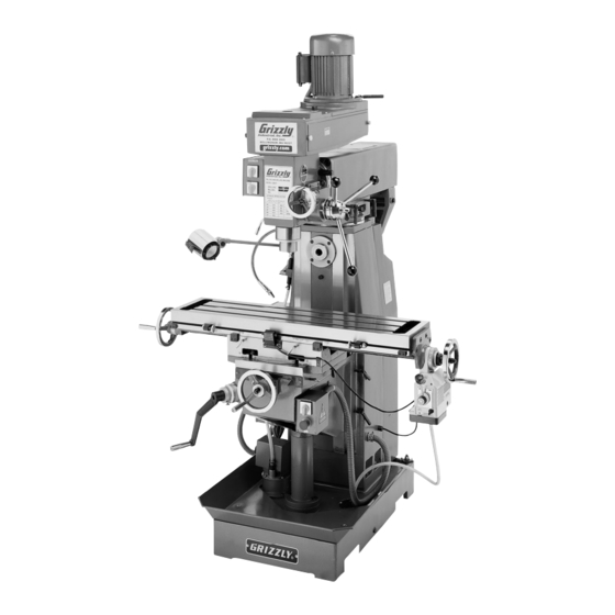
Identification Figure 1. The following is a list of controls and components on the Model G3616/G3617. Please take time to become familiar with each term and its location. These terms will be used throughout the manual and knowing them is essential to understanding the instructions and terminology used in this manual. -
Page 7: G3616 Machine Data Sheet
G3616 Machine Data Sheet MACHINE DATA SHEET Customer Service #: (570) 546-9663 · To Order Call: (800) 523-4777 · Fax #: (800) 438-5901 MODEL G3616 VERTICAL MILL Product Dimensions: Weight................................1322 lbs. Length/Width/Height....................41-15/16 x 41-3/4 x 80-15/16 in. Foot Print (Length/Width)........................28-3/4 x 18 in. - Page 8 Spindle Bearings..........................Roller and Ball The information contained herein is deemed accurate as of 10/1/2007 and represents our most recent product specifications. Model G3616 PAGE 2 OF 3 Due to our ongoing improvement efforts, this information may not accurately describe items previously purchased.
- Page 9 Set of R-8 Collets The information contained herein is deemed accurate as of 10/1/2007 and represents our most recent product specifications. Model G3616 PAGE 3 OF 3 Due to our ongoing improvement efforts, this information may not accurately describe items previously purchased.
-
Page 10: G3617 Machine Data Sheet
The information contained herein is deemed accurate as of 10/1/2007 and represents our most recent product specifications. Model G3617 PAGE 1 OF 3 Due to our ongoing improvement efforts, this information may not accurately describe items previously purchased. G3616/G3617 Mill... - Page 11 The information contained herein is deemed accurate as of 10/1/2007 and represents our most recent product specifications. Model G3617 PAGE 2 OF 3 Due to our ongoing improvement efforts, this information may not accurately describe items previously purchased. G3616/G3617 Mill...
- Page 12 The information contained herein is deemed accurate as of 10/1/2007 and represents our most recent product specifications. Model G3617 PAGE 3 OF 3 Due to our ongoing improvement efforts, this information may not accurately describe items previously purchased. G3616/G3617 Mill...
-
Page 13: Section 1: Safety
MACHINERY. Everyday eyeglasses only or jewelry which may get caught in moving have impact resistant lenses, they are parts. Wear protective hair covering to con- NOT safety glasses. tain long hair and wear non-slip footwear. G3616/G3617 Mill... - Page 14 Undersized cords overheat and reduce Know and avoid conditions that cause the voltage. Replace extension cords if they workpiece to be ejected. become damaged. DO NOT use extension cords for 220V machinery. 25. ALWAYS LOCK MOBILE BASES BEFORE OPERATING MACHINERY. G3616/G3617 Mill...
-
Page 15: Additional Safety Instructions For Mills
Like all power tools, there is danger asso- No list of safety guidelines can be complete. ciated with the Model G3616/G3617 Mill. Every shop environment is different. Always Accidents are frequently caused by lack consider safety first, as it applies to your of familiarity or failure to pay attention. -
Page 16: Section 2: Circuit Requirements
Amperage Draw Figure 2. 6-15 plug and receptacle. The 2 HP vertical spindle motor on the Model G3616/G3617 is the largest motor on the machine and it will draw the following amps, when com- bined with the coolant pump motor: 220V Connection ........ -
Page 17: Grounding
(G7947 110V kit is #P7947600; G7948 110V conversion kit is #P7948600. To rewire the G3616/G3617 for 110V: Rewire the spindle motor(s) and the coolant motor as shown on the junction box cover on each motor. -
Page 18: Section 3: Set Up
Unpacking Wear safety glasses dur- ing the entire set up pro- The Model G3616/G3617 was carefully packed cess! when it left our warehouse. If you discover the machine is damaged after you have signed for delivery, please immediately call Customer Service at (570) 546-9663 for advice. -
Page 19: Inventory
In the event that any nonproprietary parts are missing (e.g. a nut or a washer), we would be glad to replace them, or for the sake of expedi- ency, replacements can be obtained at your local hardware store. G3616/G3617 Mill... -
Page 20: Hardware Recognition Chart
Hardware Recognition Chart G3616/G3617 Mill... -
Page 21: Clean Up
Remove this protective coating with a sol- vent cleaner or citrus-based degreaser such as Grizzly’s G7895 Degreaser. To clean thoroughly, some parts may need to be removed. For opti- mum performance from your machine, make... - Page 22 " lag bolts and washers. Use the level to make sure the table is flat along its travel. If it is not level, insert steel shims under the mill. Once the mill is level, finish tightening the bolts. G3616/G3617 Mill...
-
Page 23: Way Cover Installation
Handle Installation Attach the way cover with the four screws Locations removed in Step 1. Figure 12. Locations for handle installation. Screws (two each side) Figure 11. Way cover mounted in the correct location on the machine. G3616/G3617 Mill... -
Page 24: Section 4: Operation
Figure 13. Cutting speed table for HSS cutting ning any projects. Regardless of the con- tools. tent in this section, Grizzly Industrial will not be held liable for accidents caused by Measure the diameter of your cutting tool in lack of training. - Page 25 Move the front belt to the desired position. MIDDLE You will need to move the center pulley set in order to accomplish this. Move the center pulley set back to position MOTOR 1300 and tighten the nut. Figure 16. Horizontal spindle speed chart. G3616/G3617 Mill...
-
Page 26: Turning Spindle On
10. Tighten the nut to secure the center pulley set. 11. Close the access cover by inserting the hand Horizontal Spindle screw, then connect the machine to the ON/OFF Switch power source. Figure 19. Horizontal spindle ON/OFF switch. G3616/G3617 Mill... -
Page 27: Loading Tools
To load a tool in the horizontal spindle (G3617 only): Make sure the spindle is turned OFF. Clean any debris from the spindle opening. Rotate the vertical spindle 90º. Rotate the spindle box 180º so that the spindle support is in-line with the horizontal spindle axis. G3616/G3617 Mill... -
Page 28: Unloading Tools
(Figure 22) and rotate it either clockwise or counterclockwise until the spindle is in the desired position. Remove the handle and return it to the knee travel nut. Tighten the two linear lock handles to lock the travel. G3616/G3617 Mill... - Page 29 Tighten the three nuts to lock the spindle in Figure 24. Vertical and horizontal rotation place, and push in the lock pin as far as it will components. Note: For accurate positioning, additional setup tools should be used to determine the actual angular setting. G3616/G3617 Mill...
-
Page 30: Table Rotation
Vise Rotation Make sure the power is turned OFF. Remove as many items from the mill table The Model G3616/G3617 comes equipped with as possible. This will make rotating the table a milling vise. The vise has a swivel base that easier. -
Page 31: Table Travel
The longitudinal feed is controlled by two handwheels, one at each end of the table, and two locks at the front of the table (see Figures 28 & The table of the Model G3616/G3617 can be 30). moved in 3 axes: Cross Feed, Longitudinal Feed, and Knee Feed. -
Page 32: Quill Travel
Quill Travel Power Feed Quill Feed Control The Model G3616/G3617 comes equipped with a power feed option on the longitudinal travel. The The quill feed is controlled by the handle on the power feed has the following options (see Figure right of the spindle and a lock on the left. -
Page 33: Coolant System
Coolant System Make sure the mill has been properly lubri- cated. The Model G3616/G3617 is equipped with a cool- ant system (see Figure 36), which should be filled Make sure the spindle area is free of obstruc- prior to starting the pump to avoid damage. -
Page 34: Section 5: Accessories
10 second vernier scales, gear drives with oil immersion and satin chrome dials. See the current Grizzly catalog for full specifica- tions. Features: 4.330" overall height (horizontal), 6.750" height to center hole (vertical), #3 Morse Taper, 0.465"... - Page 35 Figure 45. H3022 Measurement Tool Set. Features 2 flute ball nose end mills. Includes the following sizes: ", ", ", ", ", ", ", " G7897—Machining Fluid ". Figure 46. G7897 Machining Fluid. Figure 43. G9765 9 PC. Ball End Mill Set. G3616/G3617 Mill...
- Page 36 Protect yourself comfortably with a pair of cush- ioned earmuffs. Especially important if you or employees operate for hours at a time. H1302 H4979 H4977 Figure 50. G96 Gun Treatment spray. ® Figure 48. Our most popular earmuffs. G3616/G3617 Mill...
-
Page 37: Section 6: Maintenance
• Check oil level in gear box and power feed; fill if needed. Quarterly Check: Your Model G3616/G3617 requires very little • Clean out coolant tank and replace coolant. maintenance. A thorough cleaning, on a regular basis, will increase the machine durability and effi-... -
Page 38: Lubrication
Figure 51. Back of Machine Fittings. Left Side of Machine (Figures 52–54): C. Column/Knee Intersection Figure 54. Front of mill. D. Longitudinal Feed Handwheel E. Longitudinal Ways (Under Table) Cross Ways (Under Table) G. Table Rotation (Front and Back) H. Knee Feed Handwheel G3616/G3617 Mill... - Page 39 Figure 55 . Right side of mill, under table. Figure 56 . Horizontal spindle. G3616/G3617 Mill...
-
Page 40: Checking/Adding Coolant
Checking/Adding Changing Coolant Coolant The Model G3616/G3617 coolant tank holds approximately 4 gallons of coolant. We recom- mend changing this fluid every six months or A small amount of coolant is lost during normal sooner if it develops an unpleasant odor. -
Page 41: Section 7: Service
This section is provided for your convenience— it is not a substitute for the Grizzly Service Department. If any adjustments arise that are not described in this manual, then feel free to call the Grizzly Technical Support at (570) 546-9663. -
Page 42: Troubleshooting
Spindle starts, but coolant 1. Coolant pump relay tripped. 1. Press the reset button on the coolant pump relay. pump will not start. 2. Switch at fault. 2. Replace switch. 3. Pump damaged by running without 3. Replace pump. coolant present. G3616/G3617 Mill... - Page 43 2. Dull cutting tool or poor cutting tool 2. Sharpen cutting tool or select a better cutting tool selection. for the intended operation. 3. Wrong rotation of cutting tool. 3. Check for proper cutting rotation for cutting tool. G3616/G3617 Mill...
-
Page 44: Replacing V-Belts
3. Remove four screws 11. Replace the top cover and secure in place in this area. 2. Pull handle with the four Phillips head screws. towards front of machine. Figure 59. Vertical spindle access area. G3616/G3617 Mill... - Page 45 Remove the damaged V-belt and replace it. Close the access cover by inserting the knob Tighten spindle tension bolt. screw, then connect the machine to the power source. Push the upper pulley set back into position. Complete Steps 7–9 from the Horizontal Spindle instructions. G3616/G3617 Mill...
-
Page 46: Adjusting Gibs
Over-tightening may cause pre- mature wear. Spindle Head Gib Each sliding dovetail on the Model G3616/G3617 Adjustment Screw has a gib that is sandwiched between two adjust- ment screws (see Figures 61–64 for the locations of one end of each adjustment screw). -
Page 47: G3616 Wiring Box Identification
G3616 Wiring Box Identification Main Power Contactor Switch Vertical Spindle Relay Transformer Coolant Pump Relay Circuit Breaker Pump Capacitor Grounding Terminal Bar Main Terminal Bar G3616/G3617 Mill... -
Page 48: G3616 110V Wiring Diagram
G3616 110V Wiring Diagram CODE NAME SPECIFICATIONS SINGLE-PHASE MOTOR (VERTICAL) YC1000L2-4 1PH 110V/220V 60HZ 2HP 1725 RPM V1 COOLANT PUMP YDB-12TH 40W 1PH 110V/220V 60HZ 12L/MIN 3M POWER FEED AS-235 AC 110V AC CONTACTOR CJX1-32/22 AC 24V 60HZ MAIN POWER SWITCH... -
Page 49: G3616 220V Wiring Diagram
G3616 220V Wiring Diagram CODE NAME SPECIFICATIONS SINGLE-PHASE MOTOR (VERTICAL) YC1000L2-4 1PH 110V/220V 60HZ 2HP 1725 RPM V1 COOLANT PUMP YDB-12TH 40W 1PH 110V/220V 60HZ 12L/MIN 3M POWER FEED AS-235 AC 110V AC CONTACTOR CJX1-32/22 AC 24V 60HZ MAIN SWITCH... -
Page 50: G3617 Wiring Box Identification
G3617 Wiring Box Identification Contactor Main Switch Vertical Spindle Relay Transformer Horizontal Spindle Relay Circuit Breaker Grounding Terminal Bar Coolant Pump Relay Pump Main Capacitor Terminal Bar G3616/G3617 Mill... -
Page 51: G3617 110V Wiring Diagram
HZ5C-25/M4D035v COMBINATION SWITCH FOR HORIZONTAL HZ5C-25/M4D035 SPINDLE COMBINATION SWITCH FOR COOLANT PUMP HZ5C-10/M2C005 EMERGENCY STOP BUTTON LAY3-02ZS/1 2NC MICRO SWITCH LXW6-11DL LE:3A CIRCUIT BREAKER DZ47-63 (1P 3A) TRANSFORMER JBK4-200 1:0-110V 0:0-110V/120VA 0-220V 0-24V/80VA HALOGEN LAMP JC-38 (50W AC:24V) G3616/G3617 Mill... -
Page 52: G3617 220V Wiring Diagram
HZ5C-25/M4D035 COMBINATION SWITCH FOR HORIZONTAL HZ5C-25/M4D035 SPINDLE COMBINATION SWITCH FOR COOLANT PUMP HZ5C-10/M2C005 EMERGENCY STOP BUTTON LAY3-02ZS/1 2NC MICRO SWITCH LXW6-11DL LE:3A CIRCUIT BREAKER DZ47-63 (1P 3A) TRANSFORMER JBK4-200 1:0-110V 0:0-110V/120VA 0-220V 0-24V/80VA HALOGEN LAMP JC-38 (50W AC:24V) G3616/G3617 Mill... -
Page 53: Column Parts Breakdown
�� �� � �� �� � �� �� �� � �� �� �� � �� �� � �� �� � �� �� �� � �� �� �� �� �� �� �� �� �� �� �� �� �� �� G3616/G3617 Mill... -
Page 54: Column Parts List
PHLP HD SCR M5-.8 X 12 PS96M PHLP HD SCR M10-1.5 x 8 (G3617) P3616045 P3616093 VERTICAL SPINDLE SPEEDS LABEL P3616046 ADJUST SCREW M8-1.25 P3617094 HORZ SPINDLE SPEEDS LABEL PS08M PHLP HD SCR M5-.8 X 12 G8588 GRIZZLY CAST IRON LOGO PLATE G3616/G3617 Mill... -
Page 55: Rotary Table Parts Breakdown
��� ��� ��� ��� ��� ��� ��� ��� ��� ��� ��� ��� ��� ��� ��� ��� ��� ��� ��� ��� ��� ��� ��� ��� ��� ��� ��� ��� ��� ��� ��� ��� ��� ��� ��� ��� ��� ��� G3616/G3617 Mill... -
Page 56: Rotary Table Parts List
DESCRIPTION PART # DESCRIPTION P3616101 HANDLE P3616127 ADJUST SCREW M8-1.25 P3616102 HANDLE COLLAR P3616128 LONG LEAD SCREW (G3616) PN09M HEX NUT M12-1.75 P3617128 LONG LEAD SCREW (G3617) PK96M KEY 3 X 3 X 20 P3617129 WAY COVER PLW05M LOCK WASHER 12MM... -
Page 57: Head Parts Breakdown
��� ��� ��� ��� ��� ��� ��� ��� ��� ��� ��� ��� ��� ��� ��� ��� ��� ��� ��� ��� ��� ��� ��� ��� ��� ��� ��� ��� ��� ��� ��� ��� ��� ��� ��� ��� ��� ��� G3616/G3617 Mill... -
Page 58: Head Parts List
ARBOR R-8 X P3617235 HANDLE BAR P3616283 DRILL CHUCK P3617236 FEED SHAFT KNOB M12-1.75 P3616284 WEDGE SHIFTER P3616237 HANDLE P3616285 G3616 MACHINE ID LABEL P3616238 HANDLE COLLAR KNOB P3617285 G3617 MACHINE ID LABEL P3616239 SCALE P3616286 SECONDARY WARNINGS LABEL P3616240 RIVET P3616287... -
Page 59: G3617 Horizontal Spindle Parts Breakdown
��� ��� ��� ��� ��� ��� ��� ��� ��� ��� ��� ��� ��� ��� ��� ��� ��� ��� ��� ��� ��� ��� ��� ����� ��� ����� ��� ��� ����� ����� ��� ��� ����� ����� ��� ����� ��� ��� G3616/G3617 Mill... -
Page 60: G3617 Horizontal Spindle Parts List
1-1/4" HORIZONTAL ARBOR PR11M EXT RETAINING RING 25MM 386-1 P3617386-1 1-1/4" ARBOR NUT P3617340 KEY 8 X 8 X 50 386-2 P3617386-2 1-1/4" ARBOR SLEEVE P3617341 MOTOR BASE 386-3 P3617386-3 1-1/4" ARBOR SPACER PSB124M CAP SCREW M12-1.75 X 80 G3616/G3617 Mill... -
Page 61: Power Feed Parts Breakdown
��� ��� ����� ����� ����� ����� ��� ����� ����� ����� ��� ����� ��� ������ ����� ��� ��� ������ ����� ��� ������ ����� ��� ����� ����� ����� ��� ����� ����� ����� ����� ����� ����� ��� ����� ������ ����� ����� G3616/G3617 Mill... -
Page 62: Power Feed Parts List
501-1 P3616501-1 MICRO SWITCH HOLDER 510-6 P3616510-6 BEARING COVER 501-2 P3616501-2 SWITCH ACTUATOR 510-7 P3616510-7 BEARING 501-3 P3616501-3 PIN ACTUATOR 510-8 PRP02M ROLL PIN 3 X 16 501-4 P3616501-4 MICRO SWITCH 510-9 PRP02M ROLL PIN 3 X 16 G3616/G3617 Mill... -
Page 63: Power Feed Parts List, Continued
512-1-1 P3616512-1-1 X CONTROL HANDLE DISC 514-5 PS17M PHLP HD SCR M4-.7 X 6 512-1-2 P3616512-1-2 Y,Z CONTROL HANDLE DISC P3616515 RAPID SWITCH BUTTON 514-1-1 PN03M HEX NUT M8-1.25 515-1 P3616515-1 RAPID SWITCH PLUNGER 514-1-2 P3616514-1-2 POTENTIOMETER WASHER G3616/G3617 Mill... -
Page 64: G3616 Electrical Parts Breakdown
G3616 Electrical Parts Breakdown ��� ��� ��� ��� ��� ��� ��� ��� ��� ����� ��� ��� ����� ����� ����� ��� ��� ��� ��� ��� ��� ��� ��� ��� ��� ��� ��� ��� ��� ��� ��� ��� ��� ��� ��� ���... -
Page 65: G3616 Electrical Parts List
G3616 Electrical Parts List PART # DESCRIPTION PART # DESCRIPTION P3616601 HALOGEN LAMP P3616620 E-STOP BUTTON LAY3-02ZS/1 601-1 P3616601-1 BULB P3616621 MAIN WIRING BOX W/LATCH 601-2 P3616601-2 BULB COVER PSB33M CAP SCREW M5-.8 X 12 601-3 P3616601-3 BULB COVER RETAINER... -
Page 66: G3617 Electrical Parts Breakdown
��� ��� ��� ��� ��� ��� ��� ��� ��� ��� ��� ��� ��� ��� ��� ��� ��� ��� ��� ��� ��� ��� ��� ��� ��� ��� ��� ��� ��� ��� ��� ��� ��� ��� ��� ��� ��� ��� G3616/G3617 Mill... -
Page 67: G3617 Electrical Parts List
STRAIN RELIEF 13MM P3616610 STRAIN RELIEF 20MM P3616637 CONDUIT 10MM P3617622 HORIZONTAL SWITCH BOX P3616628 CIRCUIT BREAKER DZ47-63(1P,3A) P3616623 MAIN WIRING BOX W/LATCH PLABEL-14 ELECTRICITY LABEL PW02M FLAT WASHER 5MM P3617650 110V CONVERSION KIT PLW01M LOCK WASHER 5MM G3616/G3617 Mill... -
Page 68: Warranty And Returns
G3616/G3617 Mill... -
Page 69: Warranty Card
Would you recommend Grizzly Industrial to a friend? _____ Yes _____No Would you allow us to use your name as a reference for Grizzly customers in your area? Note: We never use names more than 3 times. _____ Yes _____No 10. - Page 70 FOLD ALONG DOTTED LINE Place Stamp Here GRIZZLY INDUSTRIAL, INC. P.O. BOX 2069 BELLINGHAM, WA 98227-2069 FOLD ALONG DOTTED LINE Send a Grizzly Catalog to a friend: Name_______________________________ Street_______________________________ City______________State______Zip______ TAPE ALONG EDGES--PLEASE DO NOT STAPLE...
- Page 71 WARRANTY AND RETURNS Grizzly Industrial, Inc. warrants every product it sells for a period of 1 year to the original purchaser from the date of purchase. This warranty does not apply to defects due directly or indirectly to misuse, abuse, negligence, accidents, repairs or alterations or lack of maintenance.
- Page 72 ��� ������ ��� ���� ���� ������� � �������� ������ ��� � ����� ������ � ����� ��� ������� ����� ��� �������� ��� ������� �� ��� �������� ������� � � ������ �������� � ������ ������� ������ �� ����� � ������ �������� ������ ��� ���� ����...
Need help?
Do you have a question about the G3616 and is the answer not in the manual?
Questions and answers