Grizzly EXTREME Series Owner's Manual
Hide thumbs
Also See for EXTREME Series:
- Owner's manual (92 pages) ,
- Manual (68 pages) ,
- Manual insert (32 pages)
Table of Contents
Advertisement
Quick Links
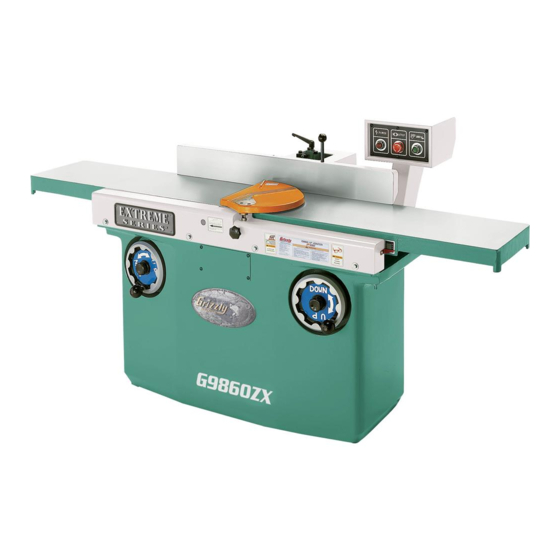
MODEL G9860, G9860ZX,
G9953ZX, & G9953ZXF
EXTREME SERIES JOINTER
OWNER'S MANUAL
(For models manufactured since 10/20)
COPYRIGHT © NOVEMBER, 2008 BY GRIZZLY INDUSTRIAL, INC., REVISED OCTOBER, 2020 (KS)
WARNING: NO PORTION OF THIS MANUAL MAY BE REPRODUCED IN ANY SHAPE
OR FORM WITHOUT THE WRITTEN APPROVAL OF GRIZZLY INDUSTRIAL, INC.
#TS11249 PRINTED IN TAIWAN
V6.10.20
Advertisement
Table of Contents

Related Manuals for Grizzly EXTREME Series


Summary of Contents for Grizzly EXTREME Series
- Page 1 OWNER'S MANUAL (For models manufactured since 10/20) COPYRIGHT © NOVEMBER, 2008 BY GRIZZLY INDUSTRIAL, INC., REVISED OCTOBER, 2020 (KS) WARNING: NO PORTION OF THIS MANUAL MAY BE REPRODUCED IN ANY SHAPE OR FORM WITHOUT THE WRITTEN APPROVAL OF GRIZZLY INDUSTRIAL, INC.
- Page 2 This manual provides critical safety instructions on the proper setup, operation, maintenance, and service of this machine/tool. Save this document, refer to it often, and use it to instruct other operators. Failure to read, understand and follow the instructions in this manual may result in fire or serious personal injury—including amputation, electrocution, or death.
-
Page 3: Table Of Contents
Table of Contents INTRODUCTION ..........................3 Manual Accuracy .........................3 Contact Info ..........................3 Machine Description ........................3 Identification ..........................4 Model Specification Comparison ....................5 SECTION 1: SAFETY ........................6 Safety Instructions for Machinery ....................6 Additional Safety Instructions for Jointers ...................8 SECTION 2: POWER SUPPLY ......................9 Model G9953ZXF 440V Conversion ..................11 SECTION 3: SETUP ........................ - Page 4 SECTION 8: WIRING ........................48 Wiring Safety Instructions ......................48 G9860 & G9860ZX Wiring Diagram ..................49 G9953ZX Wiring Diagram ......................50 G9953ZXF 220V Wiring Diagram .....................51 G9953ZXF 440V Wiring Diagram .....................52 SECTION 9: PARTS ........................53 G9860/ZX Cabinet ........................53 G9860/ZX Cutterhead & Motor ....................54 G9860/ZX Fence ........................56 G9860/ZX Table ........................58 G9860/ZX Handwheel .......................59...
-
Page 5: Introduction
“shave” off the sur- face of the workpiece. Since only a small amount of the workpiece is removed during a jointer cut, most jointer cuts are repeated many times to yield a desired result. Extreme Series Jointer (Mfd. Since 10/20) -
Page 6: Identification
Always use hold-down or push blocks when jointing material narrower than 3" or planing material thinner than 3". e) Never perform jointing, planing, or rabbeting cuts on pieces shorter than 12" in length. Extreme Series Jointer (Mfd. Since 10/20) -
Page 7: Model Specification Comparison
Construction Table Precision Ground Cast Iron Construction 1 @ 5" Dust Port Country of Taiwan (ISO 9001 Factory) Origin 1200 lbs. 1200 lbs. 1650 lbs. 1650 lbs. Weight Figure 2. Model specification comparison chart. Extreme Series Jointer (Mfd. Since 10/20) -
Page 8: Section 1: Safety
Never operate under the influence of drugs or injury or blindness from flying particles. Everyday alcohol, when tired, or when distracted. eyeglasses are NOT approved safety glasses. Extreme Series Jointer (Mfd. Since 10/20) - Page 9 EXPERIENCING DIFFICULTIES. If at any time debris. Make sure they are properly installed, you experience difficulties performing the intend- undamaged, and working correctly BEFORE ed operation, stop using the machine! Contact our operating machine. Technical Support at (570) 546-9663. Extreme Series Jointer (Mfd. Since 10/20)
-
Page 10: Additional Safety Instructions For Jointers
Straight knives should never project MAXIMUM CUTTING DEPTH. To reduce risk of more than ⁄ " (0.125") from cutterhead body. kickback, never cut deeper than ⁄ " per pass. Extreme Series Jointer (Mfd. Since 10/20) -
Page 11: Section 2: Power Supply
Current Carrying Prongs meets the specified circuit requirements. 6-20 PLUG Grounding Pin Figure 3. Typical 6-20 plug and receptacle. Extreme Series Jointer (Mfd. Since 10/20) - Page 12 (Refer to Voltage Conversion instructions for details.) Full-Load Current Rating ..... 7 Amps Nominal Voltage ......440V/480V Cycle ............60 Hz Phase ............ 3-Phase Rated Size ........... 15 Amps Connection ..Hardwire with Locking Switch -10- Extreme Series Jointer (Mfd. Since 10/20)
-
Page 13: Model G9953Zxf 440V Conversion
Any extension cord used with this machine must be in good condition and contain a ground wire and matching plug/receptacle. Additionally, it must meet the following size requirements: Minimum Gauge Size ......12 AWG Maximum Length (Shorter is Better)..50 ft. -11- Extreme Series Jointer (Mfd. Since 10/20) - Page 14 Figure 8. Illustration of motor wired for 440V operation. Replace the motor junction box cover and access panel before connecting the jointer to power. Figure 7. Accessing the light bulb from the rear of the control panel. -12- Extreme Series Jointer (Mfd. Since 10/20)
-
Page 15: Section 3: Setup
Save the containers and all packing materials for possible inspection by the carrier or its agent. Otherwise, filing a freight claim can be difficult. When you are completely satisfied with the condi- tion of your shipment, inventory the contents. -13- Extreme Series Jointer (Mfd. Since 10/20) -
Page 16: Inventory
— T-Handle Driver ........1 — Torx Bits T-20 ........15 — Indexable Inserts 14 x 14 x 2mm ..10 — Flat Head Torx Screws T-20 M6-1 x 15.. 30 Figure 10. Cleaner/degreasers available from Grizzly. -14- Extreme Series Jointer (Mfd. Since 10/20) -
Page 17: Site Considerations
Lock entrances to the shop Figure 13. Typical fasteners for mounting to or disable start switch or concrete floors. power connection to prevent unsupervised use. -15- Extreme Series Jointer (Mfd. Since 10/20) -
Page 18: Moving & Assembling Jointer
Remove the four pre-installed cap screws from the back of the jointer, then, with assis- tance, secure the pedestal to the jointer with these cap screws, as shown in Figure 15. Figure 15. Installing control panel pedestal. -16- Extreme Series Jointer (Mfd. Since 10/20) - Page 19 As you mount the jointer to the floor, use the precision level to make sure the table is level from side-to-side and from front-to-back. -17- Extreme Series Jointer (Mfd. Since 10/20)
- Page 20 Step 1. Slide the flat washer onto the fence lock shaft, insert the shaft into the hole on the top of the fence assembly and through the slot of the support. -18- Extreme Series Jointer (Mfd. Since 10/20)
-
Page 21: Adjusting Cutterhead Guard Tension
Re-test and, if necessary, repeat Step 4 until the guard has the correct tension. -19- Extreme Series Jointer (Mfd. Since 10/20) - Page 22 TDC. — If your outfeed table height is correctly set, no further adjustments are necessary. Continue with Step 6. — If the height setting is not correct, continue with Step 5. -20- Extreme Series Jointer (Mfd. Since 10/20)
- Page 23 Jam Nut recheck until the knife or insert moves the straightedge only ⁄ ". Figure 25. Table stop bolt (viewed from underneath the table). Re-install the motor access cover, fence assembly, and cutterhead guard. -21- Extreme Series Jointer (Mfd. Since 10/20)
-
Page 24: Dust Collection
Figure 26. Dust hose attached to dust port. Tug the hose to make sure it does not come off. Note: A tight fit is necessary for proper OFF Button performance. Figure 27. Resetting the stop button. -22- Extreme Series Jointer (Mfd. Since 10/20) -
Page 25: Recommended Adjustments
Call Tech Support for help. Table Parallelism (Page 44). • Model G9953ZXF Only: Press the stop but- • Model G9860 Knife Height (Page 39). ton to turn the machine OFF and observe the cutterhead rotation. -23- Extreme Series Jointer (Mfd. Since 10/20) -
Page 26: Section 4: Operations
NOT disconnect the machine from power! Keep these items away from moving parts at all ON Button: Turns the motor ON. The stop button times to reduce this risk. must be reset before this button will work. -24- Extreme Series Jointer (Mfd. Since 10/20) - Page 27 Cutterhead Brake: Turns the machine OFF and Fence Lock: Locks the fence assembly in place. brings the cutterhead to a rapid stop when the handle is rotated. Fence Tilt Handle: Tilts the fence when the tilt lock is loose. -25- Extreme Series Jointer (Mfd. Since 10/20)
-
Page 28: Stock Inspection & Requirements
Attempting to pro- cess any other synthetic or natural material 1" Min. will damage the cutterhead and cause injury Figure 35. Minimum stock dimensions for the hazards for the operator. jointer. 12" Min. -26- Extreme Series Jointer (Mfd. Since 10/20) -
Page 29: Squaring Stock
ALWAYS make sure the jointer is OFF and Figure 37). disconnected from power before performing adjustments, maintenance, or service on the machine! Previously Surface Planed Face Figure 37. Surface planing on a thickness planer. -27- Extreme Series Jointer (Mfd. Since 10/20) -
Page 30: Surface Planning
Keep your hands safe! DO Removed NOT allow them to get any closer than 4" to Surface the cutterhead. Figure 41. Illustration of surface planing results. Repeat Step 7 until the entire workpiece sur- face is flat. -28- Extreme Series Jointer (Mfd. Since 10/20) -
Page 31: Edge Jointing
Keep your hands safe! DO NOT allow them to get any closer than 4" to Figure 43. Illustration of edge jointing results. the cutterhead. Repeat Step 7 until the entire workpiece edge is flat. -29- Extreme Series Jointer (Mfd. Since 10/20) -
Page 32: Bevel Cutting
Keep your hands safe! DO NOT allow them to get any closer than 4" to the cutterhead. Removed Surface Repeat Step 7 until the bevel cut is satisfac- tory. Figure 45. Illustration of bevel cutting results. -30- Extreme Series Jointer (Mfd. Since 10/20) -
Page 33: Section 5: Accessories
® ment knives in HSS or Cobalt steel. Figure 46. Model T21992 Power Twist V-Belt. ® Figure 48. Dispoz-A-Blade Holder and Knife. ® www.grizzly.com 1-800-523-4777 order online at or call -31- Extreme Series Jointer (Mfd. Since 10/20) - Page 34 Gun Treatment 4.5 oz Spray ® Figure 50. Recommended products for protect- ing unpainted cast iron/steel part on machinery. Figure 52. Model G0862 3 HP Portable Cyclone Dust Collector. www.grizzly.com 1-800-523-4777 order online at or call -32- Extreme Series Jointer (Mfd. Since 10/20)
-
Page 35: Section 6: Maintenance
Lubricate the table elevation gears and leadscrew (Page 34). Note: This maintenance schedule is based on average usage. Adjust the maintenance schedule to match your actual usage to keep your jointer running smoothly and to protect your investment. -33- Extreme Series Jointer (Mfd. Since 10/20) -
Page 36: Lubrication
Use a shop rag and mineral spirits to clean away debris and grime from these points. Add a small amount of lubricant, then move the component to distribute the lubricant. Gears Leadscrew Figure 54. Table elevation gears and leadscrew. -34- Extreme Series Jointer (Mfd. Since 10/20) -
Page 37: V-Belts
With assistance, raise the motor assembly up Figure 55. V-belts and pulleys. until you can roll the V-belts off the pulleys. Replace the V-belts with a new, matched set, then properly tension them as instructed above. -35- Extreme Series Jointer (Mfd. Since 10/20) -
Page 38: Section 7: Service
5. Tighten mounting bolts; relocate/shim machine. 6. Motor fan rubbing on fan cover. 6. Fix/replace fan cover; replace loose/damaged fan. 7. Motor bearings at fault. 7. Test by rotating shaft; rotational grinding/loose shaft requires bearing replacement. -36- Extreme Series Jointer (Mfd. Since 10/20) - Page 39 2. Stock has excessive bow or warp. 2. Surface plane one face to use against the convex after jointer fence. jointing. 3. Insufficient number of passes. 3. Increase number of passes until the workpiece face is flat. -37- Extreme Series Jointer (Mfd. Since 10/20)
-
Page 40: Infeed Table Stop Bolt
50–55 inch/ pounds. Note: If you use the included air pressure torque wrench, refer to the detailed instruc- tions on the next page for its use. Figure 58. Insert rotating sequence. -38- Extreme Series Jointer (Mfd. Since 10/20) -
Page 41: Air Pressure Torque Wrench
20 PSI on the gauge. Set the direction switch for clockwise rotation and the setting dial to 2. -39- Extreme Series Jointer (Mfd. Since 10/20) - Page 42 Note: Since the height of the knives is set from the outfeed table height, the next step is crucial to correctly adjusting the knives. Jack Screw Figure 61. Knife correctly positioned in the cutterhead. -40- Extreme Series Jointer (Mfd. Since 10/20)
- Page 43 17. Repeat Step 15 again, but final tighten each gib bolt. 18. Replace the motor access cover, the fence assembly, and the cutterhead guard. Jack Screw Access Hole Figure 62. Jack screw access hole. -41- Extreme Series Jointer (Mfd. Since 10/20)
-
Page 44: Setting Fence Stops
Figure 64. Fence stop controls. Figure 66. Setting the fence to 45° (135°), with the cutterhead guard removed for clarity. Adjust the 45° set screw until it just touches the tilting arm, then re-tighten the jam nut. -42- Extreme Series Jointer (Mfd. Since 10/20) - Page 45 Figure 65 on Page 42, adjust fence to the square, then tighten fence tilt lock to secure setting. Tighten stop bolt toward fence assembly until it becomes snug, then tighten jam nut. -43- Extreme Series Jointer (Mfd. Since 10/20)
-
Page 46: Adjusting Table Parallelism
Note: If your jointer uses a knife-style cutterhead, you will also have to adjust the knives as the last procedure to bring the outfeed table surface and cutting edges of the knives to the same height. -44- Extreme Series Jointer (Mfd. Since 10/20) - Page 47 Outfeed Table Feeler Gauge Spiral Cutterhead Straightedge Outfeed Infeed Figure 71. Front table cover removed to expose the table adjustment bolts. Figure 70. Checking the outfeed table for the correct height above the cutterhead. -45- Extreme Series Jointer (Mfd. Since 10/20)
- Page 48 Step 9. tables. Continue this process until the table height is correct and the same from front-to-back. Note: Make sure the straightedge is not in contact with a knife or insert. -46- Extreme Series Jointer (Mfd. Since 10/20)
- Page 49 Page 39. after the other, in very small increments (see Figure 73). Rear Infeed Adjustment Bolt Locations Front Figure 74. Locations of the infeed table adjustment bolts. -47- Extreme Series Jointer (Mfd. Since 10/20)
-
Page 50: Section 8: Wiring
Technical Support at (570) 546-9663. The photos and diagrams included in this section are best viewed in color. You can view these pages in color at www.grizzly.com. -48- Extreme Series Jointer (Mfd. Since 10/20) -
Page 51: G9860 & G9860Zx Wiring Diagram
Electrical Pedestal TECO Contactor CU-18 220V Ground Ground WARNING! SHOCK HAZARD! Disconnect power before working on wiring. Control Panel Ground Ground Motor 220VAC NEMA 6-20 Plug (As Recommended) -49- Extreme Series Jointer (Mfg. Since 10/20) READ ELECTRICAL SAFETY ON PAGE 48! -
Page 52: G9953Zx Wiring Diagram
G9953ZX Wiring Diagram Electrical Pedestal TECO Contactor CU-27 220V TECO O/L Relay RHU-80A2 Ground Ground Cutterhead Brake Switch Control Panel Ground Motor NEMA L6-30 L6-30 PLUG (as recommended) -50- Extreme Series Jointer (Mfg. Since 10/20) READ ELECTRICAL SAFETY ON PAGE 48! -
Page 53: G9953Zxf 220V Wiring Diagram
G9953ZXF 220V Wiring Diagram Electrical Pedestal TECO Contactor CU-18 220V TECO O/L Relay RHU-10 Ground Ground Cutterhead Brake Switch Control Panel Motor Ground 220VAC 3-Phase Locking Disconnect Switch (As Recommended) -51- Extreme Series Jointer (Mfg. Since 10/20) READ ELECTRICAL SAFETY ON PAGE 48! -
Page 54: G9953Zxf 440V Wiring Diagram
G9953ZXF 440V Wiring Diagram Electrical Pedestal TECO Contactor CU-18 440V TECO O/L Relay RHU-10 Ground Ground Cutterhead Brake Switch Control Panel Motor Ground 440VAC 3-Phase Locking Disconnect Switch (As Recommended) -52- Extreme Series Jointer (Mfg. Since 10/20) READ ELECTRICAL SAFETY ON PAGE 48! -
Page 55: Section 9: Parts
SET SCREW M8-1.25 X 8 P9860014 ON BUTTON 35V2 P9860035V2 DUST CHUTE 5" V2.10.20 P9860015 STOP BUTTON 236V2 P9860236V2 CONTACTOR TECO CU-18 220V V2.05.08 P9860016 POWER LAMP 237V4 P9860237V4 OL RELAY TE LR97D25M7 5-25A V4.09.11 -53- Extreme Series Jointer (Mfd. Since 10/20) -
Page 56: G9860/Zx Cutterhead & Motor
G9860 cutterhead G9860/ZX Cutterhead & Motor -54- Extreme Series Jointer (Mfd. Since 10/20) - Page 57 FLAT HD TORX T20 M6-1 X 15 P9860ZX120 SPECIAL HEX NUT M17-1.5 P9860ZX802 INDEXABLE INSERT 14 X 14 X 2MM P9860ZX122 FLAT WASHER 10MM P9860ZX803 SPIRAL CUTTERHEAD 12" P9860ZX701 MOTOR 3HP 220V 1PH -55- Extreme Series Jointer (Mfd. Since 10/20)
-
Page 58: G9860/Zx Fence
G9860/ZX Fence Model G9860 18-1 -56- Extreme Series Jointer (Mfd. Since 10/20) - Page 59 P9860604 BRAKE CASING P9860209 UPPER FENCE ROD P9860605 ROLL PIN 3 X 18 P9860210 EXT RETAINING RING 16MM P9860606 SET SCREW M6-1 X 6 P9860211 CAP SCREW M5-.8 X 20 P9860607 COMPRESSION SPRING -57- Extreme Series Jointer (Mfd. Since 10/20)
-
Page 60: G9860/Zx Table
CAP SCREW M8-1.25 X 25 P9860306 COVER P9860403 SPRING SHAFT HOUSING P9860307 PHLP HD SCR M6-1 X 12 P9860404 SPRING SHAFT P9860308 J-ROD LONG P9860405 CAP SCREW M12-1.75 X 20 P9860309 TENSION SPRING -58- Extreme Series Jointer (Mfd. Since 10/20) -
Page 61: G9860/Zx Handwheel
EXT RETAINING RING 22MM P9860521 HEX NUT 3/8"-16 P9860510 SPECIAL FLAT WASHER D12 X 8MM P9860522 SPECIAL NUT M25-1.5 P9860511 LOCK KNOB M10-1.5 X 20MM P9860523 SET SCREW M6-1 X 6 P9860512 HANDWHEEL KNOB 3/8"-16 -59- Extreme Series Jointer (Mfd. Since 10/20) -
Page 62: G9953Zx/Zxf Cabinet
PHLP HD SCR M6-1 X 12 40V3 P9953ZX040V3 OL RELAY TECO RHU-10 15-20A V3.01.11 P9953ZX019 STOP COLLAR 40V3 P9953ZXF040V3 OL RELAY TECO RHU-10 15-20A V3.01.11 P9953ZX020 SET SCREW M8-1.25 X 8 P9953ZXF042 440V CONVERSION KIT -60- Extreme Series Jointer (Mfd. Since 10/20) -
Page 63: G9953Zx/Zxf Cutterhead
CUTTERHEAD PULLEY P9953ZX901 FLAT HD TORX T20 M6-1 X 15 P9953ZX111 CUTTERHEAD STOP PLATE P9953ZX902 INDEXABLE INSERT 14 X 14 X 2 P9953ZX112 END CAP P9953ZX903 SPIRAL CUTTERHEAD BODY P9953ZX117 LOCK WASHER 10MM -61- Extreme Series Jointer (Mfd. Since 10/20) -
Page 64: G9953Zx/Zxf Fence
G9953ZX/ZXF Fence -62- Extreme Series Jointer (Mfd. Since 10/20) - Page 65 FENCE ADJUSTMENT HANDLE P9953ZX244 FLAT WASHER 5/16 P9953ZX221 FLAT WASHER 6MM P9953ZX245 HEX NUT M8-1.25 P9953ZX222 SET SCREW M6-1 X 10 P9953ZX246 SET SCREW M8-1.25 X 40 P9953ZX223 SET SCREW M6-1 X 8 -63- Extreme Series Jointer (Mfd. Since 10/20)
-
Page 66: G9953Zx/Zxf Table
G9953ZX/ZXF Table -64- Extreme Series Jointer (Mfd. Since 10/20) - Page 67 P9953ZX803 CAP SCREW M5-.8 X 15 P9953ZX301 OUTFEED TABLE P9953ZX804 HANDLE P9953ZX302 NOISE DAMPER P9953ZX805 HEX NUT 5/16"-24 P9953ZX303 COVER P9953ZX806 FLAT WASHER 5MM P9953ZX304 TABLE PIVOT ROD (LONG) P9953ZX807 LOCK WASHER 5MM -65- Extreme Series Jointer (Mfd. Since 10/20)
-
Page 68: G9953Zx/Zxf Handwheel
EXT RETAINING RING 22MM P9953ZX521 HEX NUT 3/8"-16 P9953ZX510 SPECIAL FLAT WASHER D12 X 8MM P9953ZX522 SPECIAL NUT M25-1.5 P9953ZX511 LOCK KNOB M10-1.5 X 20MM P9953ZX523 SET SCREW M6-1 X 6 P9953ZX512 HANDWHEEL KNOB 3/8"-16 -66- Extreme Series Jointer (Mfd. Since 10/20) -
Page 69: G9953Zx/Zxf Motor
P9953ZXF708 KEY 7 X 7 X 65 P9953ZXF702 MOTOR PULLEY P9953ZXF709 SET SCREW M8-1.25 X 20 P9953ZXF703 LOCK WASHER 10MM P9953ZXF710 MOTOR MOUNT PLATE P9953ZXF704 HEX BOLT M10-1.5 X 40 P9953ZXF711 V-BELT A50 -67- Extreme Series Jointer (Mfd. Since 10/20) -
Page 70: Labels & Cosmetics
Safety labels help reduce the risk of serious injury caused by machine hazards. If any label comes off or becomes unreadable, the owner of this machine MUST replace it in the original location before resuming operations. For replacements, contact (800) 523-4777 or www.grizzly.com. -68-... -
Page 71: Warranty & Returns
WARRANTY & RETURNS Grizzly Industrial, Inc. warrants every product it sells for a period of 1 year to the original purchaser from the date of purchase. This warranty does not apply to defects due directly or indirectly to misuse, abuse, negligence, accidents, repairs or alterations or lack of maintenance.
Need help?
Do you have a question about the EXTREME Series and is the answer not in the manual?
Questions and answers