Table of Contents
Advertisement
Quick Links
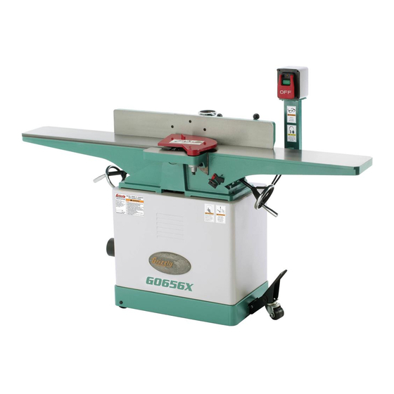
the Model g0656X is the same machine as the Model g0656, except it has a spiral cutterhead. Besides
the differences noted in this insert, all other content in the Model g0656 owner's manual applies to this
machine. Before operating your new machine, you Must read and understand this insert and the entire
Model g0656 manual to reduce the risk of injury when using this machine.
If you have any further questions about this manual insert or the differences between the Model G0656X
and the Model G0656, contact our Technical Support at (570) 546-9663 or email techsupport@grizzly.
com.
machine inventory
refer to the inventory photos in the g0656
Manual on page 11. after all the parts have been
removed from the crate, you should have the fol-
lowing items:
Wood crate:
a. Jointer assembly ........................................ 1
b. Cutterhead guard ....................................... 1
c. handwheels ................................................ 2
d. handles ...................................................... 2
e. Fence tilt lever ......................................... 1
f.
push Blocks ................................................ 2
g. spiral Cutterhead hardware (not shown)
— inserts 14 x 14 x 2 .................................. 5
— Flat head torx screws t20 M6-1 x 15 10
—l-Wrench torx t20 ................................. 1
—Driver Bit torx t20 ................................. 1
h. tool hardware Bag
— hex Wrenches 2.5, 3, 4, 6mm ..........1 Ea
—open-End Wrench 8/10, 12/14mm .....1Ea
the Model g0656X Cardboard Box and assembly
Fastener Components are identical to the cor-
responding components listed on page 11 of the
g0656 Manual.
Copyright © DECEMBEr, 2008 By grizzly inDustrial, inC. rEVisED January, 2009 (Bl)
Warning: no portion of this manual may be reproduced in any shape
or form Without the Written approval of grizzly industrial, inc.
w/spiral cutterhead
setting outfeed table height
the outfeed table height Must be level with the
carbide inserts when they are at top-dead-center.
if the outfeed table is set too low, the workpiece will
be tapered from front to back. if the outfeed table
is set too high, the workpiece will hit the edge of
Qty
the outfeed table during operation, increasing the
chance of kickback.
to set the outfeed table height:
1.
DisConnECt JointEr FroM poWEr!
2.
Move the cutterhead guard out of the way or
remove it, and open the rear access panel.
3.
place a straightedge on the outfeed table
so it extends over the cutterhead and rotate
the cutterhead pulley until one of the carbide
inserts is at top-dead-center (tDC), as shown
in figure 1.
figure
#Bl11411 printED in China
model g0656X
8" Jointer
manual insert
1
. Cutterhead insert at top-dead-center.
Advertisement
Table of Contents

Subscribe to Our Youtube Channel
Related Manuals for Grizzly Jointer w/ Spiral Cutterhead G0656X


Summary of Contents for Grizzly Jointer w/ Spiral Cutterhead G0656X
-
Page 1: Setting Outfeed Table Height
Model g0656 manual to reduce the risk of injury when using this machine. If you have any further questions about this manual insert or the differences between the Model G0656X and the Model G0656, contact our Technical Support at (570) 546-9663 or email techsupport@grizzly. com. -
Page 2: Replacing Carbide Inserts
Customer service at (800) 523-4777 and order part p0452z002, replacement Carbide insert 14x14x2mm. inward Mark outfeed table. - Page 3 to rotate or change a carbide insert: 1. DisConnECt JointEr FroM poWEr! 2. Move the cutterhead guard out of the way, or remove it. 3. remove any sawdust from the head of the carbide insert torx screw. 4. remove the torx screw and carbide insert. 5.
-
Page 4: Machine Data
8" JOINTER w/SPIRAL CUTTERHEAD & MOBILE BASE Product Dimensions: Shipping Dimensions: Box #1 Box #2 Electrical: Motors: Main Main Specifications: Operation Information Model G0656X MACHINE DATA SHEET MODEL G0656X Page 1 of 2 g0656X Manual insert... - Page 5 Cutting Capacities Cutterhead Information Table Information Construction Other Infomation Other Specifications: Features: Model G0656X g0656X Manual insert Page 2 of 2...
-
Page 6: Table Parts Breakdown
table parts breakdown g0656X Manual insert... - Page 7 REF PART # DESCRIPTION P0452Z009 L-WRENCH TORX T20 P0452Z001 DRIVER BIT TORX T20 PSS01M SET SCREW M6-1 X 10 P0656005 PULLEY P0656006 RIGHT BEARING SUPPORT BLOCK P0656007 STUD PLW06M LOCK WASHER 10MM PN02M HEX NUT M10-1.5 P6204 BALL BEARING 6204ZZ PK74M KEY 6 X 6 X 35 P0452Z002...
- Page 8 fence parts breakdown g0656X Manual insert...
-
Page 9: Fence Parts List
REF PART # DESCRIPTION PS14M PHLP HD SCR M6-1 X 12 PW03M FLAT WASHER 6MM P0656103 HANDWHEEL P0656104 BUSHING PSS85M SET SCREW M6-1 X 45 PN01M HEX NUT M6-1 PB20M HEX BOLT M8-1.25 X 35 P0656108 KNOB M10-1.5 P0656109 STUD M10-1.5 PN03M HEX NUT M8-1.25 P0656111... -
Page 10: Stand Parts Breakdown
stand parts breakdown -10- g0656X Manual insert... -
Page 11: Stand Parts List
PART # DESCRIPTION P0656201 CABINET PLN04M LOCK NUT M8-1.25 PW01M FLAT WASHER 8MM P0656204 WHEEL P0656205 SLEEVE PB86M HEX BOLT M8-1.25 X 65 P0656207 PLASTIC GROMMET PN08 HEX NUT 3/8-16 P0656209 ADJUSTING FOOT PN02 HEX NUT 5/16-18 PW07 FLAT WASHER 5/16 P0656212 MOTOR BRACKET P0656213... -
Page 12: Label Placement
(800) 523-4777 or www.grizzly.com to order new labels. -12-... - Page 13 Key 4 x 4 x 12 (Right Handwheel) ... 1 COPYRIGHT © FEBRUARY, 2008 BY GRIZZLY INDUSTRIAL, INC. WARNING: NO PORTION OF THIS MANUAL MAY BE REPRODUCED IN ANY SHAPE OR FORM WITHOUT THE WRITTEN APPROVAL OF GRIZZLY INDUSTRIAL, INC. 8" JOINTER w/BUILT-IN Clean Up The following sliding surfaces must be cleaned: •...
- Page 14 Remove the locking nut and flat washer (Figure 3) from the fence lock handle bolt (Figure 4), place the fence assembly over the jointer tables and fence bracket, and insert the bolt through the fence bracket slot, making sure the carriage fits over the key (Figure 3).
- Page 15 8" JOINTER w/BUILT-IN MOBILE BASE OWNER'S MANUAL COPYRIGHT © NOVEMBER, 2007 BY GRIZZLY INDUSTRIAL, INC. WARNING: NO PORTION OF THIS MANUAL MAY BE REPRODUCED IN ANY SHAPE OR FORM WITHOUT THE WRITTEN APPROVAL OF GRIZZLY INDUSTRIAL, INC. #BL10198 PRINTED IN CHINA...
- Page 16 ���� ������ �������� �������� ������ ������������ �� ��� ������ ������ ���������� ����������� ��� ������� �� ���� ������������������ ������� �� ����� ���������� ��� ������ ��� ������������ ����� �� ���� ������ ��� ������ �� ������� �������� ������� ��������� ����������� ������������� �� ������ ���...
-
Page 17: Table Of Contents
INTRODUCTION ... 2 Foreword ... 2 Contact Info ... 2 Machine Data Sheet ... 3 Identification ... 5 SECTION 1: SAFETY ... 6 Safety Instructions for Machinery ... 6 Additional Safety Instructions for Jointers ... 8 SECTION 2: CIRCUIT REQUIREMENTS ... 9 220V Operation ... -
Page 18: Introduction
We are proud to offer the Model G0656 8" Jointer with Built-In Mobile Base. This machine is part of a growing Grizzly family of fine woodworking machinery. When used according to the guide- lines set forth in this manual, you can expect years of trouble-free, enjoyable operation and proof of Grizzly’s commitment to customer satis-... -
Page 19: Machine Data Sheet
Machine Data Sheet ������������������������������������������������������������������������������������������ �� ������� �� ������ ���� ������� ����������� �������� � �������������������������������������������������������������������������������������������������������������������������������������������������������������������������� �������� ��������������������������������������������������������������������������������������������������������������������������������������������������������� �� �������������������������� � �������������������������������������������������������������������������������������������������������������������������������������� �� �������� ����������� ��� �� ����� � �������������������������������������������������������������������������������������������������������������������������������������������������������������� ���������� ������������������������������������������������������������������������������������������������������������������������������������������������������������������������ ������� ������������������������������������������������������������������������������������������������������������������������������������������������������������������������� �������� ������������������������������������������������������������������������������������������������������������������������������������������������ �������� ��� �� ����� � �������������������������������������������������������������������������������������������������������������������������������������������������������������������������� ����������������������������������������������������������������������������������������������������������������������������������������������������������������������������... - Page 20 ������� ���������� �������������������������������������������������������������������������������������������������������������������������������������������������� �������������������� ��������������������� � ������������������������������������������������������������������������������������������������������������������������������������������������� �� ��������������������������������������������������������������������������������������������������������������������������������������������������������������������� ������������������������ � ����������������������������������������������������������������������������������������������������������������������������������������� �������������������������� � ����������������������������������������������������������������������������������������������������������������������������������������� ����� ����������� ����������������� � ������������������������������������������������������������������������������������������������������������������������������������������������������������ ���������������������������������������������������������������������������������������������������������������������������������������������������������������������������� ��� ������������������������������������������������������������������������������������������������������������������������������������������������������������������������������� �� ������������������������������������������������������������������������������������������������������������������������������������������������������������������������������� ���������������������������������������������������������������������������������������������������������������������������������������������������������������������������� ����������������������������������������������������������������������������������������������������������������������������������������������������������� ����������� ������������������������������������������� � ��������������������������������������������������������������������������������������������������������� ������ ���������� ����������� ���������������� � ��������������������������������������������������������������������������������������������������������������������������������������������������� ������� ������������������������������������������������������������������������������������������������������������������������������������������������������������������������� �� ���������������������������������������������������������������������������������������������������������������������������������������������������������������������...
-
Page 21: Identification
G0656 8" Jointer with Built-In Mobile Base Identification Figure 1. Model G0656 identification. A. Outfeed Table B. Fence C. Cutterhead Guard D. Fence Adjustment Wheel E. Fence Tilt Handle ON/OFF Switch G. Infeed Table H. Fence Tilt Lock Outfeed Table Lock Fence Lock K. -
Page 22: Section 1: Safety
������� �� ������ ��� ���� ��� ������� ���� ����������� ������ ������ ��������� ���� ������� ��� ������� �� ������ ������� �� �� ������� ���� ��������� �� �������� ��������� ����������� ���� ������ ���� � ������ �� ������� ��� ������ ����� �������� �� ������ ��� ����� �� ���������� ��... - Page 23 ������ ������������ ��� ��������� �� ���� ����� ������� ��� ����� ���� ���������� ��������� �� ������� ����������� ����� ����� � �������������������������������������������� ����������� �� ���� �������� ��� �������� ����� ����� ���� ��������� ���� ��������� �� ����� ���� ������������������������� �� ���� �������� ������������ ���� ����������...
-
Page 24: Additional Safety Instructions For Jointers
Additional Safety Instructions for Jointers JOINTER KICKBACK. "Kickback" is when the workpiece is thrown off the jointer table by the force of the cutterhead. Always use push blocks and safety glasses to reduce the likelihood of injury from “kickback.” If you do not understand what kickback is, or how it occurs, DO NOT operate this machine. -
Page 25: Section 2: Circuit Requirements
SECTION 2: CIRCUIT REQUIREMENTS 220V Operation Serious personal injury could occur if you connect the machine to power before com- pleting the setup process. DO NOT connect the machine to the power until instructed later in this manual. Electrocution or fire could result if machine is not grounded and installed in compliance with electrical... -
Page 26: Section 3: Setup
SECTION 3: SETUP Setup Safety This machine presents serious injury hazards to untrained users. Read through this entire manu- al to become familiar with the controls and opera- tions before starting the machine! Wear safety glasses dur- ing the entire setup pro- cess! This machine and its com- ponents are very heavy. -
Page 27: Inventory
Inventory The following is a description of the main compo- nents shipped with your machine. Lay the compo- nents out to inventory them. Note: If you can't find an item on this list, check the mounting location on the machine or examine the packaging materials carefully. -
Page 28: Hardware Recognition Chart
Hardware Recognition Chart -12- G0656 8" Jointer with Built-In Mobile Base... -
Page 29: Clean Up
The unpainted surfaces are coated with a waxy oil to prevent corrosion during shipment. Remove this protective coating with a solvent cleaner or citrus-based degreaser such as Grizzly’s G7895 Citrus Degreaser. To clean thoroughly, some parts must be removed. For optimum performance from your machine, clean all moving parts or sliding contact surfaces. -
Page 30: Assembly
Assembly To assemble the jointer: Carefully lay the stand on its side so you can access the underside. Bolt the wheel assembly to the stand with the provided hardware, as shown in Figure 7. Note: Refer to the Inventory List on Page 11 for a list of components needed for ass- sembly. - Page 31 Slide the motor upward, and place the V-belt around the cutterhead pulley and the motor pulley. 10. Slide the motor down to rest on the V-belt. 11. Place a straightedge against both pulleys (Figure 10) and check the alignment of the two pulleys to make sure that they are aligned and that the V-belt is straight up and down (see Figure 11).
- Page 32 19. Using a 2.5mm hex wrench, thread the set screw through the hole in the forked end of the cutterhead guard shaft (Figure 14). Note: Thread the set screw far enough to prevent the guard from being pulled out. Figure 14. Example of installing cutterhead guard set screw.
-
Page 33: Dust Collection
Dust Collection DO NOT operate the Model G0656 without an adequate dust collection system. This jointer creates substantial amounts of wood dust while operating. Failure to use a dust collec- tion system can result in short and long-term respiratory illness. Recommended CFM at Dust Port: 400 CFM Do not confuse this CFM recommendation with the rating of the dust collector. -
Page 34: Test Run
—If your outfeed table is correctly set, no adjustments are necessary. —If the knife lifts the straightedge off the table or the table is below the straight- edge, adjust the outfeed table height with the handwheel until the straightedge just touches a knife at its highest point of rota- tion. -
Page 35: Section 4: Operations
OMMEND that you read books, trade maga- zines, or get formal training before begin- ning any projects. Regardless of the con- tent in this section, Grizzly Industrial will not be held liable for accidents caused by lack of training. G0656 8" Jointer with Built-In Mobile Base... -
Page 36: Basic Controls
Since the workpiece is held firmly against the fence as it passes over the cutterhead, the fence controls the angle of the cut. The jointer fence can be moved 45° in either direction from square and locked in place anywhere within this range. The jointer fence also features stops that allow it to be quickly set at 45°, 90°, and 125°. -
Page 37: Stock Inspection & Requirements
Stock Inspection & Requirements Here are some rules to follow when choosing and jointing stock: • DO NOT joint or surface plane stock that contains large or loose knots. Injury to the operator or damage to the workpiece can occur if a knot becomes dislodged during the cutting operation. -
Page 38: Squaring Stock
Squaring Stock Squaring stock involves four steps performed in the order below: 1. Surface Plane On The Jointer—The con- cave face of the workpiece is surface planed flat with the jointer. 2. Surface Plane On a Thickness Planer—The opposite face of the workpiece is surface planed flat with a thickness planer. -
Page 39: Edge Jointing
To surface plane on the jointer: Read and understand SECTION 1: SAFETY, beginning on Page 6. Make sure your stock has been inspected for dangerous conditions as described in the Stock Inspection & Requirements instruc- tions, beginning on Page 21. Set the cutting depth for your operation. -
Page 40: Bevel Cutting
To edge joint on the jointer: Read and understand SECTION 1: SAFETY, beginning on Page 6. Make sure your stock has been inspected for dangerous conditions as described in the Stock Inspection & Requirements instruc- tions, beginning on Page 21. Set the cutting depth for your operation. -
Page 41: Rabbet Cutting
To bevel cut on the jointer: Read and understand SECTION 1: SAFETY, beginning on Page 6. Make sure your stock has been inspected for dangerous conditions as described in the Stock Inspection & Requirements instruc- tions, beginning on Page 21. Set the cutting depth for your operation. - Page 42 To rabbet cut on the jointer: Read and understand SECTION 1: SAFETY, beginning on Page 6. Make sure your stock has been inspected for dangerous conditions as described in the Stock Inspection & Requirements instruc- tions, beginning on Page 21. Set the cutting depth for your operation.
-
Page 43: Section 5: Accessories
ACCESSORIES SECTION 5: ACCESSORIES H9815—Power Twist V-Belt - ® Smooth running with less vibration and noise than solid belts. The Power Twist customized in minutes to any size—just add or remove sections to fit your needs. Size: replaces all "A" sized V-belts. Requires two Power Twist V-belts to replace the stock V-belt on the ®... - Page 44 G5562—SLIPIT 1 Qt. Gel ® G5563—SLIPIT 12 oz Spray ® G2871—Boeshield T-9 12 oz Spray ® G2870—Boeshield T-9 4 oz Spray ® H3788—G96 Gun Treatment 12 oz Spray ® H3789—G96 Gun Treatment 4.5 oz Spray ® Figure 38. Recommended products for protect- ing unpainted cast iron/steel part on machinery.
- Page 45 These traditional dial calipers are accurate to 0.001" and can measure outside surfaces, inside surfaces, and heights/depths. Features stainless steel, shock resistant construc- tion and a dust proof display. An absolute treat for the perfectionist! Figure 45. Grizzly cartridge filters. Dial Calipers. ® -29-...
-
Page 46: Section 6: Maintenance
SECTION 6: MAINTENANCE Always disconnect power to the machine before performing maintenance. Failure to do this may result in serious person- al injury. Schedule For optimum performance from your machine, follow this maintenance schedule and refer to any specific instructions given in this section. Daily Check: •... -
Page 47: Cleaning
Fence: Place one or two drops of light machine oil on the fence pivot points (Figure 48) as needed. Figure 48. Fence lubrication locations. Cleaning Vacuum excess wood chips and sawdust, and wipe off the remaining dust with a dry cloth—this ensures moisture from wood dust does not remain on bare metal surfaces. -
Page 48: Section 7: Service
SECTION 7: SERVICE Review the troubleshooting and procedures in this section to fix or adjust your machine if a problem devel- ops. If you need replacement parts or you are unsure of your repair skills, then feel free to call our Technical Support at (570) 546-9663. - Page 49 Motor & Electrical Continued Symptom Possible Cause Machine has vibra- 5. Motor mount loose/broken. tion or noisy opera- 6. Machine is incorrectly mounted or sits tion. unevenly. 7. Motor fan is rubbing on fan cover. 8. Motor bearings are at fault. 9.
-
Page 50: Inspecting Knives
Inspecting Knives The height of the knives can be easily and quickly inspected with the knife setting gauge. This inspection will ensure that the knives are set to the correct height in the cutterhead. Tools Needed Knife Setting Gauge ... 1 To inspect the knives: DISCONNECT JOINTER FROM POWER SOURCE! - Page 51 Remove the cutterhead guard from the table and lower the infeed and outfeed tables as far as they go. This will give you unrestricted access to the cutterhead. Remove the rear access panel to expose the cutterhead pulley. Rotate the cutterhead pulley to give you good access to one of the cutterhead knives.
-
Page 52: Setting Infeed Table
Setting Infeed Table The infeed table height is set by calibrating the depth scale, and adjusting the positive stop bolts and depth stop lever. Tools Needed Straightedge ... 1 Phillips Head Screwdriver ... 1 Wrench 14mm ... 1 Hex Wrench 4mm ... 1 Calibrating Depth Scale The depth scale on the infeed table can be cali- brated or "zeroed"... -
Page 53: Setting Fence Stops
Setting Fence Stops The fence stops simplify the task of adjusting the fence to 45˚ inward, 90˚, and 45˚ outward (135˚). Tools Needed 45° Square ... 1 90° Square ... 1 Sliding Bevel ... 1 Wrench 14mm ... 1 Hex Wrench 3mm ... 1 To set the 45˚... -
Page 54: Adjusting Gibs
To set the 45˚ outward fence stop: Disengage the swing stop (see Figure 23 on Page 20). Using a sliding bevel adjusted to 135˚, adjust the fence to the 135˚ (45˚ outward) position, as shown in Figure 62. Figure 63. 45˚ outward fence stop bolt. Adjust the 45˚... -
Page 55: Wiring Diagram
��� ����� ������ ����� ���� �� ������� �� ��� ���� �� ��������� ��� �� ��� ��� ����� ���� �������� ������ ��� ��� ������ ������� ������ ��� ����� �������� ���� Figure 65. Switch wiring. Figure 66. Motor junction box and capacitor wiring. -
Page 56: Table Parts Breakdown
Table Parts Breakdown �� ���� ���� ���� �� ���� �� ���� �� �� �� �� �� �� �� �� �� �� �� �� �� �� �� �� �� �� �� -40- � � � �� � � �� �� � ��... - Page 57 REF PART # DESCRIPTION P0656001 GIB BOLT P0656002 P0656003 KNIFE PSS01M SET SCREW M6-1 X 10 P0656005 PULLEY P0656006 RIGHT BEARING SUPPORT BLOCK P0656007 STUD PLW06M LOCK WASHER 10MM PN02M HEX NUT M10-1.5 P6204 BALL BEARING 6204ZZ PK12M KEY 5 X 5 X 30 PSS53M SET SCREW M5-.8 X 12 P0656013...
-
Page 58: Fence Parts Breakdown
Fence Parts Breakdown ��� ��� ��� ��� ��� -42- ��� ��� ��� ��� ��� ��� ��� ��� ��� ��� ��� ��� ��� ��� ��� ��� ��� ��� ��� ��� ��� ��� ��� ��� ��� ��� G0656 8" Jointer with Built-In Mobile Base ���... - Page 59 REF PART # DESCRIPTION PS14M PHLP HD SCR M6-1 X 12 PW03M FLAT WASHER 6MM P0656103 HANDWHEEL P0656104 BUSHING PSS85M SET SCREW M6-1 X 45 PN01M HEX NUT M6-1 PB20M HEX BOLT M8-1.25 X 35 P0656108 KNOB M10-1.5 P0656109 STUD M10-1.5 PN03M HEX NUT M8-1.25 P0656111...
-
Page 60: Stand Parts Breakdown
Stand Parts Breakdown ����� ����� ����� ����� ����� ����� ����� ����� ��� ��� ��� ��� ��� ��� ��� ��� ����� ����� ����� ��� ����� ����� ����� ����� ����� -44- ��� ��� ��� ������ ������ ������ ������ ������ ������ ������ ������ ������... - Page 61 PART # DESCRIPTION P0656201 CABINET PLN04M LOCK NUT M8-1.25 PW01M FLAT WASHER 8MM P0656204 WHEEL P0656205 SLEEVE PB86M HEX BOLT M8-1.25 X 65 P0656207 PLASTIC GROMMET PN08 HEX NUT 3/8-16 P0656209 ADJUSTING SCREW PN02 HEX NUT 5/16-18 PW07 FLAT WASHER 5/16 P0656212 MOTOR BRACKET P0656213...
-
Page 62: Label Placement
MUST maintain the original location and readability of the labels on the machine. If any label is removed or becomes unreadable, REPLACE that label before using the machine again. Contact Grizzly at (800) 523-4777 or www.grizzly.com to order new labels. -46-... - Page 63 ���������������������������������������������������������������������������������� � ������������������������������������������������������������������������������������ ����� ����������������������� ������ � ������������������������ ���� ��������������������� ���������������������������� ������ ������������������������ ���������� � ���������������� ���������������������������� ������������������������������� ��������������������������� ��� ��������� ����������� �� ����� �� � ��������� ������ �� ���� �� ���� ��� ��������� �������� �� ���� �� ������� ������ �������� ��� ��������� �� ������� ��� ����������� �� �������� ������������� ���...
- Page 64 ���������������������� ���������������������� ����������������������������������� ����������������������������������� ������������������������������������� �������������������������������������� ������� ����������� ���� ���� ��� ���� ����������� �� ���������� �������������������������������������� ����� ����� ����...
-
Page 65: Warranty And Returns
WARRANTY AND RETURNS �������� ��� ������� �������������������������������������������������������������������������� ������������������������������������ ����������������������������������������������������������������������������������������������������������� �������������������������������������������������������������������������������������������������������������� ������������������������������������������������������������������������������������������������������������� ������������������������������������������������������������������������������������������������������������� ���������������������������������������������������������������������������������������������������������� ������������������������������������������������������������������������������������������������������������� ������������������������������������������������������������������������������������������������������� ������������������������������������������������������������������������������������������������������������������ �������������������������������������������������������������� ���������������������������������������������������������������������������������������������������������� ������ ���� �� �������� ���������� ������ ����� ��� �������� ������� ��� ���� �������� ��� ����� ��� ���� ������� ��� ���� �������� ��� ����� ���� ������� ���� ����� ����� �������� ����� �������� ������ ��� ��������� ����� ���������� ���� �������������... - Page 66 ��� ������ ��� ���� ���� ������� ����� ��� ������� ����� ��� �������� ��� ������� � � � ���� ����� ��� � � �������� ������ ��� � ����� ������ � �� ��� �������� ������� � ������ �������� ������ ������� ������ �� ����� ������...
Need help?
Do you have a question about the Jointer w/ Spiral Cutterhead G0656X and is the answer not in the manual?
Questions and answers