Table of Contents
Advertisement
Quick Links
MODEL G9901/G9902/G9903
VERTICAL MILLING MACHINE
w/POWER FEED
OWNER'S MANUAL
Model G9901
Model G9902
Model G9903
COPYRIGHT © OCTOBER, 2007 BY GRIZZLY INDUSTRIAL, INC., REVISED MARCH, 2008 (TS)
WARNING: NO PORTION OF THIS MANUAL MAY BE REPRODUCED IN ANY SHAPE
OR FORM WITHOUT THE WRITTEN APPROVAL OF GRIZZLY INDUSTRIAL, INC.
#TS9704 PRINTED IN CHINA
Advertisement
Table of Contents

Related Manuals for Grizzly G9901


Summary of Contents for Grizzly G9901
- Page 1 Model G9901 Model G9902 Model G9903 COPYRIGHT © OCTOBER, 2007 BY GRIZZLY INDUSTRIAL, INC., REVISED MARCH, 2008 (TS) WARNING: NO PORTION OF THIS MANUAL MAY BE REPRODUCED IN ANY SHAPE OR FORM WITHOUT THE WRITTEN APPROVAL OF GRIZZLY INDUSTRIAL, INC.
- Page 2 ���� ������ �������� �������� ������ ������������ �� ��� ������ ������ ���������� ����������� ��� ������� �� ���� ������������������ ������� �� ����� ���������� ��� ������ ��� ������������ ����� �� ���� ������ ��� ������ �� ������� �������� ������� ��������� ����������� ������������� �� ������ ���...
-
Page 3: Table Of Contents
Additional Safety Instructions For Mills ..15 Replacing Belts G9903 ........ 53 Glossary of Terms ........16 Replacing Brake Shoes G9901 & G9902 ..56 SECTION 2: CIRCUIT REQUIREMENTS ..17 Replacing Brake Shoes G9903 ....57 Model G9901 110/220V Operation ....17 G9901/G9902 220V, Single-Phase Model G9902 110/220V Operation .... -
Page 4: Introduction
We are proud to offer the Model G9901/G9902/ G9903 Vertical Milling Machine. This machine please write to us at the address below: is part of a growing Grizzly family of fine met- alworking machinery. When used according to Grizzly Industrial, Inc. -
Page 5: G9901 Machine Data Sheet
G9901 Machine Data Sheet ������� ���� ����� ������������������������������������������������������������������������������������������ ����� ����� �� � ��� �������� ���� ������� ���� ������� ����������� �������� � ������������������������������������������������������������������������������������������������������������������������������������������������������������������������ ��������� ��������������������������������������������������������������������������������������������������������������������������������������������������������������� ��������������� �������������������������� � �������������������������������������������������������������������������������������������������������������������������������������������� ��������� �������� ����������� ����������������������������������������������������������������������������������������������������������������������������������������������������������������������������� ���������� �������� � ������������������������������������������������������������������������������������������������������������������������������������������������������������������������� ������� ��������������������������������������������������������������������������������������������������������������������������������������������������������������������������������� ��������� �������������������� � ������������������������������������������������������������������������������������������������������������������������������������������� ���������������... - Page 6 ������ � ����������������������������������������������������������������������������������������������������������������������������������������������������� ���������������� ���������� � ���������������������������������������������������������������������������������������������������������������������������������������������������������� ��������� ���������������������������������������������������������������������������������������������������������������������������������������������������������������������� ��������� ������������������������������������������������������������������������������������������������������������������������������������������������������������������������ ��������� ����������������������������������������������������������������������������������������������������������������������������������������������������������������������������������� ����� �������������� ������������������ � �������������������������������������������������������������������������������������������������������������������������������������������������������������� ����� ��������� � �������������������������������������������������������������������������������������������������������������������������������������������������������������������������� ������ ���������������������������������������������������������������������������������������������������������������� ���������������������������������������� ��������������������������������������������������������������������������������������������������������������������������������������������������������������������������� � ������ � � ��������� ������������������������������� �������������� ������������������������������������ ����������������������� ��������������������������������� ������������������������������������ Model G9901/G9902/G9903 Milling Machine...
-
Page 7: G9902 Machine Data Sheet
���������������������������������������������������������������������������������������������������������������������������������������������������������������������������� ��� ������������������������������������������������������������������������������������������������������������������������������������������������������������������������������� �� ������������������������������������������������������������������������������������������������������������������������������������������������������������������������� � � � � � ������������������������������������������������������������������������������������������������������������������������������������������������������������������������������ ������������� � ����������������������������������������������������������������������������������������������������������������������������������������������������������������� � � � � ������������������������������������������������������������������������������������������������������������������������������������������������������������������������������ � � � � ������������������������ � �������������������������������������������������������������������������������������������������������������������������������������������� � � � � � �������������������������������������������������������������������������������������������������������������������������������������������������������������������������������� � � � � Model G9901/G9902/G9903 Milling Machine... - Page 8 ������ � ����������������������������������������������������������������������������������������������������������������������������������������������������� ���������������� ���������� � ���������������������������������������������������������������������������������������������������������������������������������������������������������� ��������� ���������������������������������������������������������������������������������������������������������������������������������������������������������������������� ��������� ������������������������������������������������������������������������������������������������������������������������������������������������������������������������ ��������� ����������������������������������������������������������������������������������������������������������������������������������������������������������������������������������� ����� �������������� ������������������ � �������������������������������������������������������������������������������������������������������������������������������������������������������������� ����� ��������� � �������������������������������������������������������������������������������������������������������������������������������������������������������������������������� ������ ���������������������������������������������������������������������������������������������������������������� ���������������������������������������� ��������������������������������������������������������������������������������������������������������������������������������������������������������������������������� � ������ � � ��������� ������������������������������� �������������� ������������������������������������ ����������������������� ��������������������������������� ������������������������������������ Model G9901/G9902/G9903 Milling Machine...
-
Page 9: G9903 Machine Data Sheet
���������������������������������������������������������������������������������������������������������������������������������������������������������������������������� ��� ������������������������������������������������������������������������������������������������������������������������������������������������������������������������������� �� ������������������������������������������������������������������������������������������������������������������������������������������������������������������������� � � � � � ������������������������������������������������������������������������������������������������������������������������������������������������������������������������������ ������������� � ����������������������������������������������������������������������������������������������������������������������������������������������������������������� � � � � ������������������������������������������������������������������������������������������������������������������������������������������������������������������������������ � � � � ������������������������ � �������������������������������������������������������������������������������������������������������������������������������������������� � � � � � �������������������������������������������������������������������������������������������������������������������������������������������������������������������������������� � � � � Model G9901/G9902/G9903 Milling Machine... - Page 10 ������ � ����������������������������������������������������������������������������������������������������������������������������������������������������� ���������������� ���������� � ���������������������������������������������������������������������������������������������������������������������������������������������������������� ��������� ���������������������������������������������������������������������������������������������������������������������������������������������������������������������� ��������� ������������������������������������������������������������������������������������������������������������������������������������������������������������������������ ��������� ����������������������������������������������������������������������������������������������������������������������������������������������������������������������������������� ����� �������������� ������������������ � �������������������������������������������������������������������������������������������������������������������������������������������������������������� ����� ��������� � �������������������������������������������������������������������������������������������������������������������������������������������������������������������������� ������ ���������������������������������������������������������������������������������������������������������������� ���������������������������������������� ��������������������������������������������������������������������������������������������������������������������������������������������������������������������������� � � ������ � ��������� ����������������������� ������������������������������� �������������� ������������������������������������ ����������������������� ��������������������������������� ������������������������������������ Model G9901/G9902/G9903 Milling Machine...
-
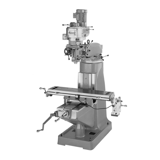
Page 11: Identification
Figure 1. Identification, left side (Model G9902 shown). A. Ram G. X-Axis (Longitudinal) Ball Handle B. Motor H. Knee C. Drive System One-Shot Oiler D. Headstock Z-Axis Lock Handle E. Table K. Column Z-Axis (Vertical Elevation) Crank Model G9901/G9902/G9903 Milling Machine... - Page 12 Q. X-Axis Table Lock Handle Forward/Reverse Power Switch M. X-Axis (Longitudinal) Limit Switch R. Y-Axis (Cross) Ball Handle N. X-Axis Limit Stop S. Knee Support O. X-Axis Ball Handle Y-Axis Table Lock Handle P. X-Axis Power Feed Unit -10- Model G9901/G9902/G9903 Milling Machine...
-
Page 13: G9901/G9902 Drive System & Headstock Controls
G9901/G9902 Drive System & Headstock Controls Figure 3. Model G9901/G9902 drive system and headstock controls. A. Spindle Brake G. Downfeed Clutch Lever B. Manual/Power Downfeed Selector H. Fine Downfeed Handwheel C. Coarse Downfeed Handle Power Downfeed Direction Pin D. Quill Locking Lever Power Downfeed Rate Dial E. -
Page 14: G9903 Drive System & Headstock Controls
D. Spindle Speed Range Lever Power Downfeed Direction Pin E. Manual/Power Downfeed Selector M. Power Downfeed Rate Dial N. Forward/Reverse Power Switch Coarse Downfeed Handle G. Quill Locking Lever O. Spindle Brake H. Dial Indicator Rod -12- Model G9901/G9902/G9903 Milling Machine... -
Page 15: Section 1: Safety
����� ������� ���������� ������������ ���� ������������������������������������� ������������������� �� ����� ������� ��������� ���� �� ������ ���� � ����� �������� ����� �� ����� ��� ��������� �� ���������� ���� ��������� ����� �� �������� ������������������ ��������� ���� �������� ������ ������������������������������������ ������������������������������������������� ����������������������������������� -13- Model G9901/G9902/G9903 Milling Machine... - Page 16 ��� ���� ������������ �������� ��� ������� ���� ����������������������������������������� ������������������������������������������� �������������������������������������������� ���� ����� ��� ����� ���� ���� �������� ��� ���� ������������������������������������� �������������������������������������������� ��� ���� ���� ������ ��� �� ����� ������������������ ��� ���� ��������� ������ ����� ���������� -14- Model G9901/G9902/G9903 Milling Machine...
-
Page 17: Additional Safety Instructions For Mills
Use this mill with respect and caution to lessen the possibility of operator injury. If normal safety precautions are overlooked or ignored, serious personal injury may occur. -15- Model G9901/G9902/G9903 Milling Machine... -
Page 18: Glossary Of Terms
The following is a list of common definitions, terms and phrases used throughout this manual as they relate to this mill and metalworking in general. Become familiar with these terms for assembling, adjusting and operating this mill. Your safety is VERY important to us at Grizzly! Arbor: A machine shaft that supports a cutting Gib: A tapered wedge located along a sliding tool. -
Page 19: Section 2: Circuit Requirements
The Model G9901 features a 110/220V motor that is prewired for 220V and draws the following amps under maximum load: Model G9901 Motor Draw at 110V ..19 Amps 6-15 Plug & Outlet Model G9901 Motor Draw at 220V ..9.5 Amps... -
Page 20: Model G9902 110/220V Operation
To change to 110V operation, the forward/ MUST ensure compliance reverse switch and the motor must be rewired. by checking with a quali- Refer to the G9901/G9902 110V Wiring Diagram fied electrician! on Page 59. -18- Model G9901/G9902/G9903 Milling Machine... -
Page 21: Model G9903 220/440V 3-Phase Operation
To change to 440V operation, the motor local and state codes. You must be rewired. Refer to the G9903 440V Wiring MUST ensure compliance Diagram on Page 61. by checking with a quali- fied electrician! -19- Model G9901/G9902/G9903 Milling Machine... -
Page 22: Section 3: Setup
Save the containers and all packing materials for possible inspection by the carrier or its agent. Otherwise, filing a freight claim can be difficult. When you are completely satisfied with the condi- tion of your shipment, inventory the contents. -20- Model G9901/G9902/G9903 Milling Machine... -
Page 23: Inventory
Remove nents out to inventory them. this protective coating with a solvent cleaner or citrus-based degreaser such as Grizzly’s G7895 Note: If you can't find an item on this list, check Citrus Degreaser. To clean thoroughly, some parts the mounting location on the machine or examine must be removed. -
Page 24: Site Considerations
C. Working Depth ........66 ⁄ " D. Working Width: Re-install and tighten the acorn nuts. — G9901 & G9902 ........60" —G9903 ..........61" Check for proper installation by rotating the ball handles. Children and visitors may be seriously injured if unsuper- vised around this machine. -
Page 25: Lifting & Moving Mill
— If the mill lifts evenly, continue to move the clear the shipping pallet and floor. mill to the permanent location. -23- Model G9901/G9902/G9903 Milling Machine... -
Page 26: Mounting To Shop Floor
NOTICE When using mounting bolts, use shims between the mill base and the floor to fill the gaps. Otherwise, the cast iron base could become warped and crack when tightening the mounting fasteners. -24- Model G9901/G9902/G9903 Milling Machine... -
Page 27: Test Run
Ensure the manual/power downfeed selec- Page 28 to understand how the power feeds tor is in the manual or "hand" position (refer and limit switches function. to Downfeed Operations on Page 35 for detailed instructions). -25- Model G9901/G9902/G9903 Milling Machine... -
Page 28: Spindle Break-In
(OFF). to make sure the gears are engaged. Turn the mill ON and let it run for 20 min- utes. Turn the mill OFF. The spindle break-in of your mill is now com- plete. -26- Model G9901/G9902/G9903 Milling Machine... -
Page 29: Section 4: Operations
Regardless of the con- tent in this section, Grizzly Industrial will • Always make sure the workpiece is firmly not be held liable for accidents caused by held to the table by clamps, fixtures, or other lack of training. -
Page 30: Table Movement
Unexpected table and workpiece move- ment could cause the cutter to bind and break apart, resulting in personal injury to the operator. Figure 19. Location of Z-axis locking handle on left side of the knee. -28- Model G9901/G9902/G9903 Milling Machine... - Page 31 G. Ball Handle. Use this handle to manually power source. position the table. Flip the ON/OFF switch up to turn the power H. Travel Graduated Dial. Marked in 0.001" feed ON. increments, each complete revolution is equal to 0.200" of table travel. -29- Model G9901/G9902/G9903 Milling Machine...
-
Page 32: Headstock Movement
If the headstock slips during milling operation, the spinning cutter could bind and break apart, causing serious personal injury or property damage. Figure 23. Headstock rotated to the right 45°. -30- Model G9901/G9902/G9903 Milling Machine... -
Page 33: Ram Movement
Rotate the ram to the desired position, and personal injury or property damage. re-tighten the rotation locking bolts to secure the ram in place. -31- Model G9901/G9902/G9903 Milling Machine... -
Page 34: Setting Rpm
Low Range (A) 78–278 Copper High Range (B) 670–2400 Cast Iron, soft Cast Iron, hard Figure 29. Model G9901/G9902 spindle speed range chart. Mild Steel Cast Steel Model G9903 Spindle Speed Ranges (RPM) Alloy Steel, hard Tool Steel Low Range 70–500... - Page 35 To avoid damage to the drive gears, make sure the mill is turned OFF and the spindle is stopped before you change the spindle speed range. Motor Spindle Pulley Pulley Figure 33. Model G9901/G9902 side belt cover removed (right side shown). -33- Model G9901/G9902/G9903 Milling Machine...
- Page 36 Motor Positioning Handle Replace the two belt covers before starting the mill. To avoid an entanglement hazard, always operate the Model G9901/G9902 mill with the two side belt covers in place. Motor Locking Handles Configuring Spindle Speed Controls (G9903) Figure 34.
-
Page 37: Downfeed Controls
When changing the spindle speed range, the spindle direction will reverse. Always know which way the spindle is spinning before moving the cutting tool into the workpiece. Figure 37. Manual/power downfeed selector in the manual or "hand" position. -35- Model G9901/G9902/G9903 Milling Machine... - Page 38 G. Downfeed Stop Locking Thumb Wheel: Locks the downfeed stop in place. H. Downfeed Clutch Lever: Engages the fine/ power downfeed gear. -36- Model G9901/G9902/G9903 Milling Machine...
-
Page 39: Spindle Brake
0.0035 0.0058 Figure 40. Power downfeed rates. Spindle Brake Lever Figure 42. Model G9901/G9902 spindle brake lever. Figure 41. Power downfeed rate dial. NOTICE Observe the fine handwheel movement, then To avoid premature wear of the brake pads,... -
Page 40: Loading/Unloading Tools
-38- Model G9901/G9902/G9903 Milling Machine... -
Page 41: Section 5: Accessories
10 second vernier scales, gear drives with oil immersion and satin chrome dials. 5µm, absolute/incremental coordinate display, arc See the current Grizzly catalog for full specifica- function, line of holes function, angled cuts func- tions. Features: 4.330" overall height (horizontal), tion, 199 user defined datum points, centering/ 6.750"... - Page 42 Features 2 flute ball nose end mills. Includes the following sizes: ", ", ", ", ", ", ", " ". Figure 54. Recommended products for protecting unpainted cast iron/steel machinery parts. Figure 52. G9765 9 PC. Ball End Mill Set. -40- Model G9901/G9902/G9903 Milling Machine...
-
Page 43: Section 6: Maintenance
Check mill base for accumulated coolant and debris. • Check for damaged or worn electrical con- nections, wires, and switch. • Check for any other condition that would hamper the safe and efficient operation of your mill. -41- Model G9901/G9902/G9903 Milling Machine... -
Page 44: Lubrication Overview
Spindle Bearings Bearing Oil Cup Table Ways & Lead Screws Elevation Lead Screw Ram Dovetail Way Figure 56. Model G9901/G9902 downfeed Spindle Spline gearing and spindle bearing oil cups. Power Feed Gearing Speed Range Gearing 1000 Figure 55. Recommended lubrication task schedule. - Page 45 ISO 68 or SAE 20 non- detergent oil to the full length of the ram way Reservoir (see Figure 60). Figure 58. Model G9901/G9902/G9903 one shot oiler. Move the table through the X, Y, and Z-axis paths to distribute the lubricant evenly.
- Page 46 (see Figures 61 & 62). Use a 19mm wrench to remove the acorn nut, and handwheel from the power feed unit (see Figure 63). Graduated Dial Figure 61. Model G9901/G9902 drawbar Retaining X-Axis access. Ring Lead Screw Figure 63. Power feed with the handwheel removed.
- Page 47 Rotate the handwheel to check the power Brush medium weight white lithium grease on feed gear operation and to distribute the the teeth of the brass gear and the smaller grease on the gears. drive gear (see Figure 65). -45- Model G9901/G9902/G9903 Milling Machine...
-
Page 48: Coolant
There are drains in the table, a bottom splash pan, and a cavity in the base of the column for the coolant pump. Refer to the Grizzly catalog or www.grizzly.com for options. If you use coolant with your mill operations, it is inevitable that some will drain through the screens in the bottom splash pan. -
Page 49: Section 7: Service
8. Use smaller sharp cutters/drill bits; reduce the feed rate; reduce the spindle RPM; use cutting fluid if pos- sible. 9. Motor is overheated. 9. Clean off motor, allow to cool, and reduce work- load. 10. Motor is at fault. 10. Test/repair/replace motor. -47- Model G9901/G9902/G9903 Milling Machine... - Page 50 2. Sharpen cutting tool or select a better cutting tool for selection. the intended operation. 3. Wrong rotation of cutting tool. 3. Check for proper cutting rotation for cutting tool. 4. Workpiece not securely clamped. 4. Properly secure workpiece. -48- Model G9901/G9902/G9903 Milling Machine...
-
Page 51: Adjusting Gibs
Adjust the gibs by turning the gib adjusting screw until you feel a slight drag when moving the sliding component. Refer to Figures 68–70 for the locations of the gib adjusting screws. Figure 70. Z-axis gib adjusting screw (left side of knee). -49- Model G9901/G9902/G9903 Milling Machine... -
Page 52: Adjusting Backlash
Re-tighten the top screw to lock the bottom screw setting. Check the amount of backlash by rotating the X-axis ball handle. Repeat Steps 3–4 if necessary. Mounting Plate Assembly Figure 73. Removing mounting plate assembly from lead screw. -50- Model G9901/G9902/G9903 Milling Machine... -
Page 53: Adjusting Downfeed Clutch Lever
Turn the adjusting screw until the clutch lever disengages, then re-tighten the locknut. Check to make sure the downfeed clutch lever disengages during downfeed opera- tion. -51- Model G9901/G9902/G9903 Milling Machine... -
Page 54: Replacing Belts G9901 & G9902
If necessary, replace the brake shoes at this time (refer to Replacing Brake Shoes G9901 & G9902 on Page 56 for detailed instructions). With assistance, lift the motor and place a Figure 76. Upper spindle cover. -
Page 55: Replacing Belts G9903
Bolt Holes Call Grizzly Customer Service at (800) 523-4777 to order the following parts: Part Description Part Number Variable Speed Belt (G9903) ....P9903727 Ribbed Timing Belt (G9903) ....P9903836... - Page 56 Figure 81. Upper bearing housing and cap Figure 83. Upper transmission case cap screws. screws. Note: Carefully pry up on the upper bearing housing, rotate it, and repeat this process until the housing comes free from the mill. -54- Model G9901/G9902/G9903 Milling Machine...
- Page 57 Note: Be sure to remove the two M6-1 x 60 bolts after securing the retaining spring plate Figure 84. Ribbed timing belt. hex nut. 16. Place a new variable speed belt around the pulley, as shown in Figure 85. Figure 85. Variable speed belt. -55- Model G9901/G9902/G9903 Milling Machine...
-
Page 58: Replacing Brake Shoes G9901 & G9902
Replace the parts of the transmission case out (see Figure 87). cover plate in the reverse order they were removed. Re-assemble the remaining parts as described in Steps 9–11 from Replacing Belts G9901 & G9902 on Page 52. -56- Model G9901/G9902/G9903 Milling Machine... -
Page 59: Replacing Brake Shoes G9903
Due to the time and labor involved, you may want to replace the belts at this time as well. Call Grizzly Customer Service at (800) 523- 4777 to order the brake shoes (Part Number P9903732). To replace the brake shoes: Complete Steps 1–14 from Replace Belts... -
Page 60: G9901/G9902 220V, Single-Phase Wiring Diagram
�� � � ������ ���������������� wiring. � �� �� ��� ��� ��� ��� �� � � ������ � � � � �� � ����� �� �� �� Figure 92. Model G9901/G9902 ������ 220V motor wiring. -58- Model G9901/G9902/G9903 Milling Machine... -
Page 61: G9901/G9902 110V, Single-Phase Wiring Diagram
110v wiring diagram g9901 G9901/G9902 110V, Single-Phase Wiring Diagram ����� ���������������� ������ � ������� ���������������������� � ������� ��� �� � � ���� ���� ���� �� ����� �� ���������������� �� � � �� �� �� � �� � � ������ ��... -
Page 62: G9903 220V, 3-Phase Wiring Diagram
��� � � � ������ � � � � � � ����� ��� �� ��� �� �� �� ��� �� �� �� �� �� �� �� �� ������ Figure 94. Model G9903 220V motor wiring. -60- Model G9901/G9902/G9903 Milling Machine... -
Page 63: G9903 440V, 3-Phase Wiring Diagram
��� ��������������� ��� ������ ��� ��� ��� ��� � � � ������ � � � � � � ����� ��� ��� �� ��� �� �� �� �� �� �� �� �� �� �� �� ������ -61- Model G9901/G9902/G9903 Milling Machine... -
Page 64: Section 8: Parts
�� �� �� �� ��� ���� �� �� �� �� ��� �� ��� �� �� �� �� �� �� �� �� �� �� ��� �� ��� �� �� �� �� �� �� �� �� ��� -62- Model G9901/G9902/G9903 Milling Machine... - Page 65 PK08M KEY 5 X 5 X 16 P9901050 WIPER HOLDER P9901099 SHAFT PS05M PHLP HD SCR M5-.8 X 8 P62042RZ BALL BEARING 62042RZ P9901052 SADDLE P9901101 SPECIAL WASHER P9901053 WIPER HOLDER P9901102 SPIRAL BEVEL GEAR -63- Model G9901/G9902/G9903 Milling Machine...
- Page 66 SPECIAL BOLT M12-1.75 X 110 P9901118 SPIDER GEAR 129-1 PN09M HEX NUT M12-1.75 P9901119 SPECIAL BOLT M12-1.75 X 120 PSS06M SET SCREW M8-1.25 X 16 P9901120 GEAR SHAFT P9901917 FORWARD/REVERSE SWITCH P9901121 LEVER P9901918 SWITCH BOX P9901122 LEVER KNOB -64- Model G9901/G9902/G9903 Milling Machine...
-
Page 67: Table Assembly Breakdown
Table Assembly Breakdown -65- Model G9901/G9902/G9903 Milling Machine... - Page 68 P9901213 LEFT TABLE BRACKET P9901235 RIGHT TABLE BRACKET PK31M KEY 4 X 4 X 30 P62042RZ BALL BEARING 62042RZ P9901215 LONG. LEAD SCREW (G9901) P9901237 SPACER P9902215 LONG. LEAD SCREW (G9902/G9903) P9901238 BUSHING P9901216 ADJUSTING SCREW M8-1.25 X 24 P9901239...
-
Page 69: Model G9901/G9902 Drive Assembly Breakdown
Model G9901/G9902 Drive Assembly Breakdown ��� ��� ��� ��� ��� ��� ��� ��� ��� ��� ����� ��� ��� ��� ��� ��� ��� ��� ��� ��� ��� ��� ��� ��� ��� ��� ��� ��� ��� ��� ��� ��� ��� ��� ���... - Page 70 Model G9901/G9902 Drive Assembly Parts List REF PART # DESCRIPTION REF PART # DESCRIPTION P9902301 DRAWBAR 24-3/16 343-5 PN01M HEX NUT M6-1 P9901302 DRAWBAR SPACER 343-6 PSB24M CAP SCREW M5-.8 X 16 P9901204 SPECIAL NUT M33 X 1.5 343-7 PLW01M...
- Page 71 MOTOR FAN COVER P9901394 CONICAL PIN 500-3 P9901500-3 S. CAP CD60,150MFD,265VAC P9901395 500-4 P9901500-4 R. CAP CBB60,20MFD,450VAC PRP56M ROLL PIN 4 X 25 500-5 P9901500-5 WIRING/CAPACITOR JUNCTION BOX P9901397 SPANNER SHAFT 500-6 P9901500-6 TERMINAL BOARD -69- Model G9901/G9902/G9903 Milling Machine...
-
Page 72: Headstock Breakdown
��� ��� ��� ��� ��� ��� ��� ��� ��� ��� ��� ��� ��� ��� ��� ��� ��� ��� ��� ��� ��� ��� ��� ��� � ��� ��� ��� ��� ��� ��� ��� ��� ��� ��� ��� -70- Model G9901/G9902/G9903 Milling Machine... - Page 73 BUSHING PR01M EXT RETAINING RING 10MM P9901547 SPECIAL WASHER P9901599 COVER P9901548 SLEEVE PSS91M SET SCREW M6-1 X 14 P9901549 BEVEL GEAR PN01M HEX NUT M6-1 P9901550 REVERSE CLUTCH PRP03M ROLL PIN 5 X 20 -71- Model G9901/G9902/G9903 Milling Machine...
- Page 74 SET SCREW M3-.5 X 14 P9901692 HEADSTOCK P9901646 FORKED ROD P9901693 OIL CUP ADAPTER P9901647 THREAD PIN P9901694 OIL CUP PSB18M CAP SCREW M4-.7 X 8 P9901695 TUBING P9901649 THREADED BUSHING 695-1 P9901695-1 COTTON WIRE P9901650 RETAINING PLATE -72- Model G9901/G9902/G9903 Milling Machine...
-
Page 75: Model G9903 Upper Drive System Breakdown
��� ��� ��� ��� ��� ��� ��� ��� ��� ��� ��� ��� ��� ��� ��� ��� ��� ��� ��� ��� ��� ��� ��� ��� ��� ��� ��� ��� ��� ��� ��� ��� ��� ��� ��� -73- Model G9901/G9902/G9903 Milling Machine... - Page 76 REGULATING RING P9903732 BRAKE SHOE P9903785 MOTOR SPLINE SLEEVE P9903734 UPPER COUPLING SHAFT P9903786 KEY 6 X 6 X 70 PSS01M SET SCREW M6-1 X 10 P9903793 SPLINE SLEEVE PK149M KEY 8 X 8 X 25 -74- Model G9901/G9902/G9903 Milling Machine...
-
Page 77: Model G9903 Lower Drive System Breakdown
��� ��� ��� ��� ��� ��� ��� ��� ��� ��� ��� ��� ��� ��� ��� ��� ��� ��� ��� ��� ��� ��� ��� ��� ��� ��� ��� ��� ��� ����� ��� ��� ��� ��� ��� -75- Model G9901/G9902/G9903 Milling Machine... - Page 78 INT RETAINING RING 68MM PSB24M CAP SCREW M5-.8 X 16 P9903843 SPACER P9903886 TIMING PULLEY PW04M FLAT WASHER 10MM PN05M HEX NUT M16-1.5 P9903847 SPECIAL BOLT P9903888 FRONT COVER P9903848 SPRING SHIM PSB39M CAP SCREW M4-.7 X 20 -76- Model G9901/G9902/G9903 Milling Machine...
-
Page 79: One-Shot Oiler Breakdown
One-Shot Oiler Breakdown -77- Model G9901/G9902/G9903 Milling Machine... - Page 80 NYLON TUBING 4 X 3 P9901912 SPECIAL NUT P9901905 LUBRICATING PUMP P9901913 MULTI-WAY JUNCTION P9901906 ADAPTER P9901914 MULTI-WAY JUNCTION PSB33M CAP SCREW M5-.8 X 12 P9901915 FITTING PSB15M CAP SCREW M5-.8 X 20 P9901916 BRONZE TUBING 4 X 0.5 -78- Model G9901/G9902/G9903 Milling Machine...
-
Page 81: Accessories Breakdown & Parts List
REF PART # DESCRIPTION REF PART # DESCRIPTION P9901921 TOOL BOX P9901925 POWER FEED LIMIT SWTICH P9901922 WRENCH 17/19MM P9901926 POWER FEED BRASS DRIVE GEAR P9901923 STANDARD SCREWDRIVER 3/8" P9901927 POWER FEED UNIT P9901924 STANDARD SCREWDRIVER 1/4" -79- Model G9901/G9902/G9903 Milling Machine... -
Page 82: Label Placement
MUST maintain the original location and readability of the labels on the machine. If any label is removed or becomes unreadable, REPLACE that label before using the machine again. Contact Grizzly at (800) 523-4777 or www.grizzly.com to order new labels. -80-... - Page 83 NOTES...
- Page 85 �������� ���� ���������������������������������������������������������������������������������� � ������������������������������������������������������������������������������������ ����� ����������������������� ������ � ������������������������ ���� ��������������������� ���������������������������� ������ ������������������������ ���������� � ���������������� ���������������������������� ������������������������������� ��������������������������� ��� ��������� ����������� �� ����� �� � ��������� ������ �� ���� �� ���� ��� ��������� �������� �� ���� �� ������� ������...
- Page 86 ���������������������� ����� ����� ���� ������� ����������� ���� ���� ��� ���� ����������� �� ���������� ���������������������� ����������������������������������� ����������������������������������� ������������������������������������� �������������������������������������� ��������������������������������������...
-
Page 87: Warranty And Returns
WARRANTY AND RETURNS Grizzly Industrial, Inc. warrants every product it sells for a period of 1 year to the original purchaser from the date of purchase. This warranty does not apply to defects due directly or indirectly to misuse, abuse, negligence, accidents, repairs or alterations or lack of maintenance. - Page 88 ��� ������ ��� ���� ���� ������� � �������� ������ ��� � ����� ������ � ����� ��� ������� ����� ��� �������� ��� ������� �� ��� �������� ������� � � ������ �������� � ������ ������� ������ �� ����� � ������ �������� ������ ��� ���� ����...
Need help?
Do you have a question about the G9901 and is the answer not in the manual?
Questions and answers