Table of Contents
Advertisement
Quick Links
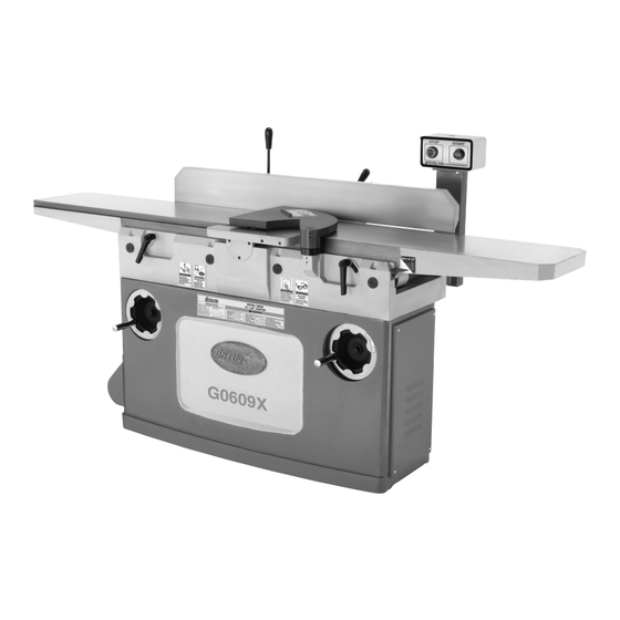
model g0609X
12" Jointer
w/spiral cutterhead
manual insert
the Model g0609X is the same as the Model g0609, except it has a spiral cutterhead. Besides the
data sheet and parts in this insert, the content in the Model g0609 owner's manual is the same for both
machines. Before operating your new machine, you MuSt read and understand this insert and the entire
Model g0609 manual to reduce the risk of injury from improper use or setup.
If you have any further questions about this manual insert or the differences between the Model g0609X
and the Model g0609, contact our Technical Support at (570) 546-9663 or email techsupport@grizzly.
com.
Copyright © SEptEMBEr, 2007 By grizzly induStrial, inC. rEviSEd July, 2008. (tr)
Warning: no portion of this manual may be reproduced in any shape
or form Without the Written approval of grizzly industrial, inc.
#tr10028 printEd in China
Advertisement
Table of Contents

Related Manuals for Grizzly G0609X


Summary of Contents for Grizzly G0609X
- Page 1 Model g0609 manual to reduce the risk of injury from improper use or setup. If you have any further questions about this manual insert or the differences between the Model g0609X and the Model g0609, contact our Technical Support at (570) 546-9663 or email techsupport@grizzly. com.
-
Page 2: Machine Data Sheet
MACHINE DATA SHEET Customer Service #: (570) 546-9663 · To Order Call: (800) 523-4777 · Fax #: (800) 438-5901 MODEL G0609X 12" JOINTER W/ SPIRAL CUTTERHEAD Product Dimensions: Weight................................884 lbs. Length/Width/Height........................84 x 33 x 43-1/2 in. Foot Print (Length/Width)........................44-1/4 x 18 in. Shipping Dimensions: Type................................ - Page 3 Cutterhead Information Cutterhead Type............................Spiral Cutterhead Diameter..........................3-7/8 in. Number of Cutter Spirals...........................4 Number of Indexable Cutters.......................... 60 Cutter Insert Type..........................Indexable Cutter Insert Length..........................14 mm Cutter Insert Width........................... 14 mm Cutter Insert Thickness..........................2 mm Cutterhead Speed..........................4950 RPM Table Information Table Length............................
- Page 4 g0609X 220v Wiring diagram CONTROL PANEL WARNING! SHOCK HAZARD! Disconnect power before working on wiring. MAGNETIC SWITCH ASSEMBLY COLOR KEY 220 VAC L6-20 PLUG (as recommended) MOTOR Model g0609X...
- Page 5 Jointer breakdown Model g0609X...
- Page 6 Jointer breakdown parts list REF PART # DESCRIPTION REF PART # DESCRIPTION P0609001 CUTTERHEAD GUARD P0609045 SHAFT PFH23M FLAT HD SCR M8-1.25 X 16 PLW06M LOCK WASHER 10MM P0609005 SPECIAL FLAT WASHER PB32M HEX BOLT M10-1.5 X 25 PSS04M SET SCREW M6-1 X 12 P0609048 BUSHING P0609007...
- Page 7 tables breakdown REF PART # DESCRIPTION REF PART # DESCRIPTION P0609101 TABLE (LEFT) PSB72M CAP SCREW M10-1.5 X 30 P0609102 TABLE LIP (LEFT) PLW06M LOCK WASHER 10MM PLW06M LOCK WASHER 10MM P0609113 DEPTH SCALE PSB84M CAP SCREW M10-1.5 X 35 P0609114 RIVET 2 X 4 P0609105...
- Page 8 fence breakdown REF PART # DESCRIPTION REF PART # DESCRIPTION P0609201 FENCE BRACKET P0609224 SPECIAL HEX NUT M12 PW06M FLAT WASHER 12MM P0609225 LEFT BRACKET PLW05M LOCK WASHER 12MM P0609226 PSB77M CAP SCREW M12-1.75 X 30 P0609227 HANDLE P0609205 SLIDING RAIL P0609228 HANDLE ROD PSB20M...
- Page 9 stand breakdown Model g0609X...
- Page 10 stand parts list PART # DESCRIPTION PART # DESCRIPTION P0609301 LEFT ACCESS DOOR PW03M FLAT WASHER 6MM 301-1 PSBS18M BUTTON HD CAP SCR M6-1 X 18 P0609326 ADAPTER 301-2 PW03M FLAT WASHER 6MM P0609327 LATCH P0609302 DUST HOOD P0609328 SMALL STRAIN RELIEF 302-1 PSBS11M BUTTON HD CAP SCR M6-1 X 10...
- Page 11 (800) 523-4777 or www.grizzly.com to order new labels. -10-...
- Page 12 g0609X accessories g3640—power twist v-belt - ⁄ " x 48" h7319—10 pk. of carbide inserts 14x14x2mm ® Smooth running with less vibration and noise than solid belts. the power twist v-belt can be ® h1411—powerhands safety stick ™ customized in minutes to any size—just add or this safety push stick features interchangeable remove sections to fit your needs.
- Page 13 315A-7 P0609315A-7 JUNCTION BOX V2.03.08 COPYRIGHT © MARCH, 2008 BY GRIZZLY INDUSTRIAL, INC. WARNING: NO PORTION OF THIS MANUAL MAY BE REPRODUCED IN ANY SHAPE OR FORM WITHOUT THE WRITTEN APPROVAL OF GRIZZLY INDUSTRIAL, INC. #BL10618 PRINTED IN CHINA...
- Page 14 12" PARALLELOGRAM JOINTER OWNER'S MANUAL COPYRIGHT © OCTOBER, 2006 BY GRIZZLY INDUSTRIAL, INC. REVISED FEBRUARY, 2008 (BL) WARNING: NO PORTION OF THIS MANUAL MAY BE REPRODUCED IN ANY SHAPE OR FORM WITHOUT THE WRITTEN APPROVAL OF GRIZZLY INDUSTRIAL, INC. #BL8452 PRINTED IN CHINA...
- Page 15 ���� ������ �������� �������� ������ ������������ �� ��� ������ ������ ���������� ����������� ��� ������� �� ���� ������������������ ������� �� ����� ���������� ��� ������ ��� ������������ ����� �� ���� ������ ��� ������ �� ������� �������� ������� ��������� ����������� ������������� �� ������ ���...
-
Page 16: Table Of Contents
Table of Contents INTRODUCTION ..........................3 Foreword ............................ 3 Contact Info ..........................3 Machine Data Sheet ........................4 Identification ..........................6 SECTION 1: SAFETY........................7 Additional Safety for Jointers ..................... 9 SECTION 2: CIRCUIT REQUIREMENTS ..................10 220V Single-Phase ........................10 SECTION 3: SET UP ........................ - Page 17 SECTION 7: SERVICE ........................32 Troubleshooting ........................32 Inspecting Knives ........................34 Adjusting/Replacing Knives ...................... 34 Checking/Adjusting Table Parallelism ..................37 Setting Outfeed Table Height ....................39 Setting Infeed Table ......................... 40 Calibrating Depth Scale ......................41 Setting Fence Stops ......................... 41 V-Belts ............................
-
Page 18: Introduction
However, owing to Grizzly’s policy of con- Web Site: http://www.grizzly.com tinuous improvement, changes may be made at any time with no obligation on the part of Grizzly. For your convenience, we always keep current Grizzly manuals available on our website at www. -
Page 19: Machine Data Sheet
Machine Data Sheet MACHINE DATA SHEET Customer Service #: (570) 546-9663 • To Order Call: (800) 523-4777 • Fax #: (800) 438-5901 MODEL G0609 12" PARALLELOGRAM JOINTER Product Dimensions: Weight ................................875 lbs. Length/Width/Height .........................84" x 33" x 43 ⁄ " Foot Print (Length/Width) ..........................44 ⁄... - Page 20 Capacity Maximum Depth of Cut ..........................⁄ " in. Maximum Rabbeting Depth ........................... ⁄ " Maximum Width of Cut ..........................12" Cutterhead Diameter ............................ 3 ⁄ " Cutterhead Knife Size ....................... 12" x ⁄ " x 1 ⁄ " Cutterhead Speed ..........................4950 RPM Cuts Per Minute ..........................
-
Page 21: Identification
Identification Figure 1. G0609 identification. A. Outfeed Table B. Fence C. Fence Lock Handle D. Fence Tilt Lever E. Cutterhead Guard Control Panel G. Infeed Table H. Depth Scale Infeed Table Lock Infeed Table Adjustment Handwheel K. Outfeed Table Lock Outfeed Table Adjustment Handwheel M. -
Page 22: Section 1: Safety
SECTION 1: SAFETY ������� �� ������ ��� ���� ��� ������� ���� ����������� ������ ������ ��������� ���� ������� ��� ������� �� ������ ������� �� �� ������� ���� ��������� �� �������� ��������� ����������� ���� ������ ���� � ������ �� ������� ��� ������ ����� �������� �� ������ ��� ����� �� ���������� ��... - Page 23 ������ ������������ ��� ��������� �� ���� ����� ������� ��� ����� ��� ������ ��������� ���� ��� ���� ���������� ��������� �� ��������������������������������������� ������� ����������� ����� ����� � ����� ���� ���������� ��������� ������� ����� �������������������������������������������� ����������������� ����������� ��� ����� ��� ������� ����� �� ���� �������� ��� �������� ����� ������...
-
Page 24: Additional Safety For Jointers
Additional Safety for Jointers JOINTER KICKBACK. "Kickback" is when MAXIMUM CUTTING DEPTH. The maxi- the workpiece is thrown off the jointer table mum cutting depth for one pass is ⁄ ". by the force of the cutterhead. Always use Never attempt any single cut deeper than push blocks and safety glasses to reduce this! the likelihood of injury from “kickback.”... -
Page 25: Section 2: Circuit Requirements
SECTION 2: CIRCUIT REQUIREMENTS 220V Single-Phase Grounding In the event of an electrical short, grounding reduces the risk of electric shock. The grounding wire in the power cord must be properly connect- ed to the grounding prong on the plug; likewise, the outlet must be properly installed and ground- Serious personal injury could occur if you ed. -
Page 26: Section 3: Set Up
SECTION 3: SET UP Set Up Safety Items Needed for Set Up The following items are needed to complete the This machine presents set up process, but are not included with your serious injury hazards machine: to untrained users. Read through this entire manu- Description al to become familiar with... -
Page 27: Inventory
Inventory After all the parts have been removed from the wood crate, you should have the following items: Crate Contents: (Figure 3 & 4) A. Jointer Assembly ........1 B. Fence Assembly ......... 1 C. Fence Bracket ..........1 D. Push Blocks ..........2 E. -
Page 28: Hardware Recognition Chart
Hardware Recognition Chart -13- G0609 12" Parallelogram Jointer... -
Page 29: Clean Up
Some residential floors may require additional Grizzly’s G7895 Degreaser. To clean thoroughly, reinforcement to support both the machine and some parts may need to be removed. For opti- operator. -
Page 30: Moving & Placing Jointer
Moving & Placing Mounting to Shop Jointer Floor Although not required, we recommend that you mount your new machine to the floor. Because this is an optional step and floor materials may The Model G0609 is vary, floor mounting hardware is not included. extremely heavy Generally, you can either bolt your machine to... -
Page 31: Fence
Fence Make sure the fence, carriage, and table have been thoroughly cleaned of all the export grease before installing the fence, or the fence will not slide easily. The fence has a keyway slot built into the underside of it that fits over the key on the table. -
Page 32: Winding Cutterhead Guard
Winding Cutterhead Pedestal Switch Guard The pedestal switch is upside down for shipping purposes. Though the cutterhead guard is pre-installed, you should check to make sure it works. Components and Hardware Needed: • Flat Washers 10mm (Pedestal) ....2 Pull the guard back and let it go. The guard •... -
Page 33: Knife Setting Jig
Knife Setting Jig �������� ������ Assemble the jig as shown in Figure 13. Figure 14. Cutterhead knife at top-dead center. When correctly set, the knife will barely touch the straightedge, as shown in Figure 15. Figure 13. Knife setting jig assembly. —... -
Page 34: Dust Port
Dust Port Test Run Once the assembly is complete, test run your machine to make sure it runs properly. DO NOT operate the Model G0609 with- If, during the test run, you cannot easily locate out an adequate dust collection system. the source of an unusual noise or vibration, stop This machine creates substantial amounts using the machine immediately, then review the... -
Page 35: Section 4: Operations
OMMEND that you read books, trade maga- zines, or get formal training before begin- ning any projects. Regardless of the con- tent in this section, Grizzly Industrial will not be held liable for accidents caused by lack of training. -20-... -
Page 36: Stock Inspection And Requirements
Table Movement: To move the infeed table, loosen the table lock (Figure 17), move the table with the table handwheel in the preset range, then tighten the table lock. The outfeed table is preset with no range of movement allowed, so if it gets accidentally unlocked it will not move. -
Page 37: Squaring Stock
Squaring Stock • Remove foreign objects from the stock. Make sure that any stock you process with the jointer is clean and free of any dirt, nails, staples, tiny rocks or any other foreign Squaring stock involves four steps performed objects that may damage the jointer blades. -
Page 38: Surface Planing
Surface Planing To surface plane on the jointer: Read and understand SECTION 1: SAFETY, beginning on Page 7. The purpose of surface planing on the jointer is to make one flat face on a piece of stock (see Inspect your stock for the dangerous con- Figures 22 &... -
Page 39: Edge Jointing
Edge Jointing To edge joint on the jointer: Read and understand SECTION 1: SAFETY, beginning on Page 7. The purpose of edge jointing is to produce a fin- ished, flat-edged surface (see Figures 24 & 25) Inspect your stock for the dangerous condi- that is suitable for joinery or finishing. -
Page 40: Bevel Cutting
Bevel Cutting To bevel cut on the jointer: Read and understand SECTION 1: SAFETY, beginning on Page 7. The purpose of bevel cutting is to cut a specific angle into the edge of a workpiece (see Figures Inspect your stock for the dangerous condi- 26 &... -
Page 41: Rabbet Cutting
Rabbet Cutting To rabbet cut on the jointer: Read and understand SECTION 1: SAFETY, beginning on Page 7. The purpose of rabbet cutting is to remove a section of the workpiece edge (see Figures 28 Inspect your stock for the dangerous con- &... -
Page 42: Section 5: Accessories
SECTION 5: ACCESSORIES G3640—Power Twist V-Belt - ⁄ " x 48" ® G3631—Jointer/Planer Knife Hone Smooth running with less vibration and noise Add a razor hone to your planer and jointer knives than solid belts. The Power Twist V-belts can ®... - Page 43 An absolute treat for Made in the USA. the perfectionist! Figure 36. H1411 PowerHands Safety Stick. ™ Figure 34. Grizzly Dial Calipers. ® G9643—8" Precision Straightedge H9247—Dispoz-A-Blade System ®...
- Page 44 G7984—Face Shield H2499—Small Half-Mask Respirator H1298—Dust Sealed Safety Glasses H3631—Medium Half-Mask Respirator H1300—UV Blocking, Clear Safety Glasses H3632—Large Half-Mask Respirator H2347—Uvex Spitfire Safety Glasses H3635—Disposable Cartridge Filter Pair P100 ® H0736—Shop Fox Safety Glasses Wood dust is a known carcinogen and has been ®...
-
Page 45: Section 6: Maintenance
SECTION 6: MAINTENANCE Cleaning Always disconnect power to the machine before Cleaning the Model G0609 is relatively easy. performing maintenance. Vacuum excess wood chips and sawdust, and Failure to do this may wipe off the remaining dust with a dry cloth. If any result in serious person- resin has built up, use a resin dissolving cleaner al injury. -
Page 46: Maintenance Log
Maintenance Log Maintenance Performed Date Approximate Hours Of Use -31- G0609 12" Parallelogram Jointer... -
Page 47: Section 7: Service
SECTION 7: SERVICE Review the troubleshooting and procedures in this section to fix your machine if a problem develops. If you need replacement parts or you are unsure of your repair skills, then feel free to call our Technical Support at (570) 546-9663. - Page 48 Table Symptom Possible Cause Possible Solution 1. Table lock is engaged or partially engaged. 1. Completely loosen the table lock. Tables are hard to adjust. 2. Table stops blocking movement. 2. Loosen/reset table positive stops. Cutting Symptom Possible Cause Possible Solution Excessive snipe (gouge in the end of 1.
-
Page 49: Inspecting Knives
Inspecting Knives — The knives are set correctly when they just touch the bottom of the straightedge in each of the straightedge positions. The height of the knives can be inspected with — If the knives do not touch the straightedge a straightedge to ensure that they are set evenly or they lift it up in any of the positions, then with the outfeed table at their highest point in the... - Page 50 Knife Setting Jig Method: Both tables are low- Tools Needed ered to fit the jig on the cutterhead, as shown in Straightedge ............1 Figure 43, and the knife heights are set to just Knife Setting Jig (Optional) ....... 1 touch the middle pad of the jig.
- Page 51 Adjusting the knife heights: Rotate the cutterhead to the first knife you started with. Slightly tighten all the gib bolts, a. Using a 3mm hex wrench, find the jack starting at the ends and working your way screws through the access holes in the to the middle by alternating left and right cutterhead (Figure 45) and rotate the (Figure 46).
-
Page 52: Checking/Adjusting Table Parallelism
Checking/Adjusting Place the straightedge on the outfeed table so it hangs over the cutterhead, and lower Table Parallelism the outfeed table until the straightedge just touches the cutterhead body, as shown in Figure 48 (rotate the cutterhead if neces- sary). If the tables are not parallel with the cutterhead or each other, then poor cutting results and kickback can occur. -
Page 53: Adjusting Table Parallelism
Checking Infeed Table Adjusting Table Parallelism To check the infeed table parallelism: For safe and proper cutting results, the tables must be parallel to the cutterhead. Adjusting them Follow all the steps for checking the outfeed to be parallel is a task of precision and patience, table parallelism to first make sure that the and may take up to one hour to complete. -
Page 54: Setting Outfeed Table Height
Set the outfeed table height (refer to the next sub-section). Set Screw Eccentric Location Bushing 10. Set the knives (refer to Page 35). 11. Reinstall the cutterhead guard and fence. Setting Outfeed Figure 52. Eccentric bushing and set screw Table Height location. -
Page 55: Setting Infeed Table
Setting Infeed Table Place the straightedge on the outfeed table so it hangs over the cutterhead, and lower the outfeed table until the straightedge is 0.062" ( ⁄ ") above the cutterhead body, as The infeed table on the Model G0609 has determined by using the feeler gauges (see positive stop bolts that, when properly set up, Figure 53). -
Page 56: Calibrating Depth Scale
Setting Fence Stops The fence stops simplify the task of adjusting the fence to 45˚ inward, 90˚, and 45˚ outward (135˚). Tools Needed 45° Square ............1 90° Square ............1 Sliding Bevel ............1 Wrench 14mm ........... 1 To set the 45˚ inward fence stop: Tilt the fence approximately 45°... - Page 57 To set the 45° outward fence stop: To set the 90˚ fence stop: Raise the stop block, loosen the fence tilt Lower the stop block against the fence, as lock, and position the fence against the 45° shown in Figure 59, and loosen the fence tilt outward positive stop bolt.
-
Page 58: V-Belts
V-Belts Pulley Alignment Inspect the V-belts closely; if you notice fraying, Pulley alignment is another important factor in cracking, glazing, or any other damage, replace power transmission and belt life. The pulleys the belts. A worn or damaged V-belt will not pro- should be parallel to each other and in the same vide optimum power transmission from the motor plane (coplaner) for optimum performance. - Page 59 Loosen the fasteners that hold the motor to Shift the motor horizontally as needed to align the brackets shown in Figure 63. the motor pulley with the cutterhead pulley. Tighten the fasteners that hold the motor to the brackets. V-belts should be parallel and aligned as shown in Figure 62.
-
Page 60: G0609 Electrical Components
G0609 Electrical Components START Switch STOP Switch Figure 64. Motor junction box. Figure 65. Control panel. To Control Panel Contactor Thermal Relay To Power To Motor Source Figure 66. Magnetic switch assembly (behind right access panel). -45- G0609 12" Parallelogram Jointer... -
Page 61: G0609 Wiring Diagram
G0609 Wiring Diagram ������� ����� �������������������� �� �� �� ����� ��� �� ����� �� �� �� ����� �� �� �� ����� �� �� �� �� �� ��� �� ���� �� �� �� �� �� �� �������� �� ����� ������� �� ��... -
Page 62: Base Assembly Parts Breakdown
Base Assembly Parts Breakdown � �� � � �� �� � �� � �� �� �� � �� �� � �� �� �� �� �� �� �� �� �� �� �� �� �� �� �� �� �� �� �� �� ��... -
Page 63: Base Parts List
Base Parts List PART # DESCRIPTION PART # DESCRIPTION P0609001 CUTTERHEAD GUARD PLW06M LOCK WASHER 10MM PFH23M FLAT HD SCR M8-1.25 X 16 PB32M HEX BOLT M10-1.5 X 25 P0609005 SPECIAL FLAT WASHER P0609048 BUSHING PSS04M SET SCREW M6-1 X 12 P0609049 WORM GEAR P0609007... -
Page 64: Table Assembly Parts Breakdown
Table Assembly Parts Breakdown ��� ��� ��� ��� ��� ��� ��� ��� ��� ��� ��� ��� ��� ��� ��� ��� ��� ��� ��� ��� Table Parts List REF PART # DESCRIPTION REF PART # DESCRIPTION P0609101 TABLE (LEFT) PSB72M CAP SCREW M10-1.5 X 30 P0609102 TABLE LIP (LEFT) PLW06M... -
Page 65: Fence Assembly Parts Breakdown
Fence Assembly Parts Breakdown ��� ��� ��� ��� ��� ��� ��� ��� ��� ��� ��� ��� ��� ��� ��� ��� ��� ��� ��� ��� ��� ��� ��� ��� ��� ��� ��� ��� ��� ��� ��� ��� ��� ��� ��� ��� ���... -
Page 66: Stand Assembly Parts Breakdown
Stand Assembly Parts Breakdown ����� ����� ����� ����� ����� ����� ����� ��� ��� ����� ��� ��� ��� ��� ��� ��� ��� ����� ��� ��� ��� ��� ��� ��� ����� ��� ��� ��� ��� ��� ��� ��� ��� ��� ��� ��� �����... -
Page 67: Stand Parts List
Stand Parts List PART # DESCRIPTION PART # DESCRIPTION P0609301 LEFT ACCESS DOOR P0609327 LATCH 301-1 PSBS18M BUTTON HD CAP SCR M6-1 X 18 P0609328 SMALL STRAIN RELIEF 301-2 PW03M FLAT WASHER 6MM PSB88M CAP SCREW M10-1.25 X 25 P0609302 DUST HOOD PLW06M LOCK WASHER 10MM... -
Page 68: Warning Label Parts List
MUST maintain the original location and readability of the labels on the machine. If any label is removed or becomes unreadable, REPLACE that label before using the machine again. Contact Grizzly at (800) 523-4777 or www.grizzly.com to order new labels. -53-... -
Page 69: Warranty And Returns
WARRANTY AND RETURNS Grizzly Industrial, Inc. warrants every product it sells for a period of 1 year to the original purchaser from the date of purchase. This warranty does not apply to defects due directly or indirectly to misuse, abuse, negligence, accidents, repairs or alterations or lack of maintenance. - Page 70 �������� ���� ���������������������������������������������������������������������������������� � ������������������������������������������������������������������������������������ ����� ����������������������� ������ � ������������������������ ���� ��������������������� ���������������������������� ������ ������������������������ ���������� � ���������������� ���������������������������� ������������������������������� ��������������������������� ��� ��������� ����������� �� ����� �� � ��������� ������ �� ���� �� ���� ��� ��������� �������� �� ���� �� ������� ������...
- Page 71 ���������������������� ����� ����� ���� ������� ����������� ���� ���� ��� ���� ����������� �� ���������� ���������������������� ����������������������������������� ����������������������������������� ������������������������������������� �������������������������������������� ��������������������������������������...
- Page 73 ��� ������ ��� ���� ���� ������� � �������� ������ ��� � ����� ������ � ����� ��� ������� ����� ��� �������� ��� ������� �� ��� �������� ������� � � ������ �������� � ������ ������� ������ �� ����� � ������ �������� ������ ��� ���� ����...
Need help?
Do you have a question about the G0609X and is the answer not in the manual?
Questions and answers