Table of Contents
Advertisement
Quick Links
Advertisement
Table of Contents

Related Manuals for SystemAir fantech DBF 110


Summary of Contents for SystemAir fantech DBF 110
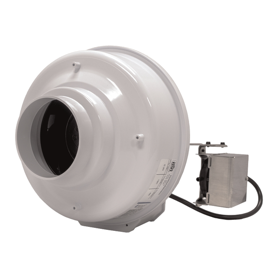
- Page 1 Installation, Operation and Maintenance instruction DBF 110 Duct Booster Fan...
-
Page 2: Table Of Contents
Table of contents 1 Introduction ............1 Product Description........1 Intended Use ..........1 Document Description ........1 Fantech Warranty ........1 Product Overview ........1 Type Designation ........2 2 Safety ..............2 Safety definitions ......... 2 Safety Instructions ........2 Personal protective equipment ....... -
Page 3: Introduction
Introduction Fantech Warranty Product Description This product is a duct boosting fan that boosts air on applica- tions such as extended duct systems, crawlspace ventilation, and dryer exhaust. This fan has rotating parts and personnel must exercise safety precautions during installation, operations, and maintenance. -
Page 4: Type Designation
Type Designation Product Name DBF 110, #95900 Duct Collar Dimensions in inches (mm.) 4 (102) Motor Type AC: Alternating Current, 1–phase Safety Caution To decrease the risk of product malfunc- Safety definitions tion or damage to the product or sur- rounding finishes and walls, read and Warnings, cautions and notes are used to point out specially obey the caution instructions that follow... -
Page 5: Installation
3.1.3 About the Pressure Switch Installation Caution To Do Before the Installation Do not move the dial on the back of the 3.1.1 To Calculate the Duct Run pressure switch. This is set at the factory at an optimal position. This product is able to overcome equivalent duct lengths up to 108 feet (34 meters) on duct systems with 4 in. -
Page 6: To Install The Product
To Install the Product 3.2.1.2 To Mount the Product in a Horizontal Position 3.2.1 To Mount the Bracket in a Caution Vertical or a Horizontal Position If you use the wrong length screws, it will damage the motor impeller. 3.2.1.1 To Mount the Product in a Vertical Position Use four (4) 1 in. - Page 7 Caution Do not connect the tubes in such a man- ner as to allow condensation from the duct to collect in the tubes. Drill a 7/16 in. (11 mm.) diameter hole in the duct wall. Carefully put the grommet into the hole. Push one end of the tube over the nipple on the control.
-
Page 8: Electrical Connection
Electrical connection To Connect the Product to the Power Supply Legend for Diagram English Terminology Meaning Motor Wires Switch Wires BROWN Brown BLACK Black BLUE Blue WHITE White GREEN Green Capacitor Line Neutral 115V Power Supply 115 Volts Power Supply Note: BROWN All motor and pressure switch connections are pre-wired... -
Page 9: Commissioning
Commissioning Operation To Commission and Test the How the Pressure Sensor Product Switch Operates The product uses a positive pressure sensing switch that rec- Note: ognizes air pressure and activates the product from an inde- pendent electrical circuit. This sequence prevents the need The procedure that follows will make sure that the product for more connections through the appliance’s circuit which works correctly. -
Page 10: Maintenance
Maintenance Warning Set the service disconnect switch in the OFF position before you do maintenance unless the instructions tell you differently. Make sure that the switch is not accidentally set in the ON position. To Maintain the Product Note: The product bearings are sealed and are supplied with an internal lubricating material. -
Page 11: Technical Data
Technical data Product Dimensions Note: Dimensions are given in inches (mm). DBF 110, 5 (127) 4 (102) 11-7/8 (302) 11 (279) 2-7/8 (73) 10-1/2 (267) #95900... - Page 12 last page Canada Latin America (800) 747 1762 (800) 565 3548 +52 55 1328 7328 support@fantech.net support@fantech.net support@fantech.net © Copyright Fantech All rights reserved Fantech reserves the rights to alter their products without notice. This also applies to products already ordered, as long as it does not affect the previously agreed specifications.
Need help?
Do you have a question about the fantech DBF 110 and is the answer not in the manual?
Questions and answers