
Related Manuals for Evonicfires 800 BLACK EDITION


Summary of Contents for Evonicfires 800 BLACK EDITION
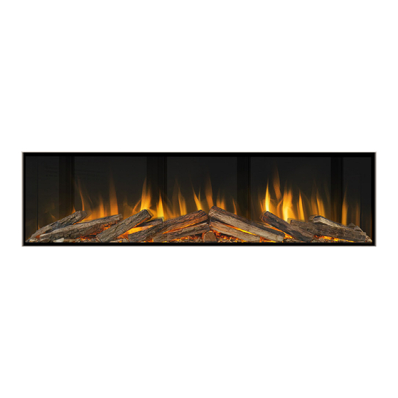
- Page 1 BLACK EDITION BLACK EDITION INSTALLATION MANUAL INSTALLATION MANUAL EVONIC - 104 INSTRUCTION MANUAL TEMPLATE ISS. 1 E-LECTRA B.E. ISS. 1...
-
Page 2: Table Of Contents
CONTENTS Health and safety ................................4 Product Dimensions .................................5 Side Panel Conversion Chart ............................6 Side Panel Configuration.............................. 7 Installation Steps ................................8 Front Glass .....................................11 Access Panel..................................13 Control Options .................................14 Remote Control .................................15 App Setup ....................................16 Using the App ..................................18 Connecting to Amazon Alexa..........................20 Connecting to Google Assistant.......................... - Page 3 EU DIRECTIVES All Evonic Fires products meet the requirements of the EC Directives. All Evonic Fires products meet the requirements of the EC Directives. These directives have been met by compliance with the following standards: These directives have been met by compliance with the following standards: EU 2011-65/EU 2015/863 Restriction of Hazardous Substances.
-
Page 4: Health And Safety
IMPORTANT INFORMATION AND HEALTH & SAFETY When using electrical appliances, basic precautions should always be followed to reduce the risk of fire, electric shock, and injury to persons, including the following: • Read all of the instructions carefully before using the appliance, only use this appliance as described in this manual. -
Page 5: Product Dimensions
PRODUCT DIMENSIONS Opening Opening Model Depth (D) Width (W) Height (H) Width (OW) Height (OH) 300mm 836mm 762mm 806mm 587mm 1000 300mm 1034mm 587mm 1004mm 414mm 1250 300mm 1285mm 587mm 1255mm 414mm 1500 300mm 1535mm 587mm 1501mm 414mm 1800 300mm 1785mm 587mm 1751mm... -
Page 6: Side Panel Conversion Chart
SIDE PANEL CONVERSION CHART 1-SIDED 2-SIDED 3-SIDED Appliance arrives in Appliance arrives in Appliance arrives in 1-sided configuration. 1-sided configuration. 1-sided configuration. Remove both side Identify which side needs Remove plaster kit from panels (Fig 1). to be removed to achieve both side panels. -
Page 7: Side Panel Configuration
REMOVING THE SIDE PANELS / CONVERTING TO GF2 or GF3 All our built-in appliances are shipped as 1 box models, with the side panels attached and the glass installed to the GF3 configuration. Please note: This does not apply to double-sided models. To convert to GF2 or GF3 configurations, you simply need to remove the side panel(s) and re-attach the plaster kit. - Page 8 CHECKS BEFORE INSTALLATION - ALL MODELS INSTALLATION DO’S AND DONT’S Before installing the appliance please read and take into account the following important requirements; • Consult a qualified professional to check the structure of the installation site. • These appliances have been designed to be installed into either a stud and plasterboard wall, or an existing chimney breast.
- Page 9 INSTALLATION METHOD - SECURING FIRE TO FRAME The appliance will come with 4 transit feet attached to the bottom - 2 at the front and 2 at the back (Fig 1). These transit brackets can also be used to secure the fireplace to your outer frame. Leave these in place if you wish to secure your fireplace to the framework using the appropriate fixings (not supplied).
-
Page 10: Installation Steps
Screw the two top mounted brackets to the wall (Fig 4). We supply masonry fixings for screwing into brick, however if you are screwing into timber, plasterboard, or another material, fixings will need to be sourced by the customer/installer. You can now construct your stud wall/s around the appliance in the design of your choosing. -
Page 11: Front Glass
GLASS INSTALLATION - FRONT GLASS First remove the bottom glass retainer bar by simply lifting out of place (Fig 1). Then you can remove the top retainer bar by unscrewing the fixings (Fig 2). Please note: Support must always be provided to the glass when removing the top retainer bar to prevent it falling forward and causing damage or injury. - Page 12 CONTINUED Then replace the top glass retainer bar and screw into place (Fig 4), and finally, replace the bottom glass retainer by slotting into place (Fig 5). Fig 4. Fig 5. EVONIC - 104 INSTRUCTION MANUAL TEMPLATE ISS. 1 E-LECTRA B.E. ISS. 1...
-
Page 13: Access Panel
ACCESS PANEL The inclusion of a small access panel is optional, but it is highly recommended as it allows for access to the fireplace’s power cord during servicing or fault-finding. The access panel can be any size, however to keep it discreet we advise around 15cm X 15cm. -
Page 14: Operation
OPERATION There are two ways to control all the features of your Evonic appliance - remote or App control. APP CONTROL REMOTE Our remote handset comes automatically paired and ready to operate straight out of the box. If you choose to control your appliance via the E-smart Cloud App your internet router and smart device should meet the following minimum requirements - Wi-Fi Router •... -
Page 15: Remote Control
REMOTE CONTROL 1. Remote Control/Handset Pairing Process: After turning on the fireplace with the rocker switch, there is a 60-second pairing window. This window begins after a beep, which occurs 15-20 seconds after the fireplace is switched on. After the first beep, press the ‘Heater ON’ button for 5 seconds until you hear a second beep. The pairing is now complete. Change Log Colour Effect Fireplace ON/OFF Log Colour Brightness Down... -
Page 16: App Setup
APP SETUP ON/OFF SWITCH Make sure that your fireplace is plugged in and the mains power is on. Download the E-Smart Cloud app from Then turn on your fireplace by pressing the Apple Store, or Google Play Store. the ON/OFF switch to the ‘ON’ position. Open the Settings panel on your device and connect to the fireplaces’... - Page 17 CONTINUED your-email@mail.com Open the settings panel on the app’s Scroll down to the ‘IoT Registration’ section and fill in your email address and create a Home Screen. password. Press ‘Save’. Then select the grey wi-fi button. Home WiFi The pairing process between your device, the Select your router from the drop down box, and fireplace, and your router will now take place.
-
Page 18: Using The App
USING THE E-SMART APP Press to turn the Control Overview fire ON or OFF Timer settings Press to turn the Shop heater ON or OFF General settings E-SMART APP SETUP On the Home Page of the E-Smart Cloud App you can see the name of your fire, the chosen temperature, and the actual temperature. -
Page 19: Control Overview
CONTROL OVERVIEW Increase temperature Target temperature Decrease temperature Speed settings Animation choice Lighting settings Log animation Flame animation brightness/speed brightness/speed Flame motor speed Fuel bed animation brightness/speed SCREEN NAVIGATION To adjust the desired temperature of your fire ensure that the heater is selected on the Home Page in To adjust the desired temperature of your fire ensure that the heater is selected on the Home Page in the previous step. -
Page 20: Connecting To Amazon Alexa
Single press Search and type in evonicfires. Single press Search and type in evonicfires. Now on the Evonicfires Halo skill page you can Now on the Evonicfires Halo skill page you can Select the Evonicfires Halo skill icon to open. - Page 21 CONTINUED... Enter the log in details that you previously Enter the log in details that you previously After a few moments your account will be After a few moments your account will be entered in the app set up process, and single entered in the app set up process, and single linked, once this is done you can single press linked, once this is done you can single press...
-
Page 22: Connecting To Google Assistant
CONNECTING TO GOOGLE HOME Once your fire is installed, and switched on, Once your fire is installed, and switched on, Single press Set up Device on the pop up list. Single press Set up Device on the pop up list. download and open the Google Home app. - Page 23 CONTINUED... Type in Evonic Fires, single press search and Type in Evonic Fires, single press search and Once in the Evoflame log in page, enter the Once in the Evoflame log in page, enter the then select the Evonic Fires E-Smart icon. then select the Evonic Fires E-Smart icon.
-
Page 24: Programming The Timer
PROGRAMMING THE TIMER Input your desired time in the Time box, Input your desired time in the Time box, select the action (Fire On/Off/, Heater On/Off) select the action (Fire On/Off/, Heater On/Off) Single press the clock icon on the Home Page Single press the clock icon on the Home Page you want. -
Page 25: Problems Connecting
PROBLEMS CONNECTING If you are having problems connecting your fireplace with your device and router please try the following steps to fix the issue. • Switch fireplace OFF • Switch wi-fi router OFF • Switch fireplace back ON (Keeping router OFF) •... -
Page 26: Voice Control Commands
COMMANDS FOR AMAZON ALEXA When using Amazon Alexa or to control your appliance settings remember to substitute the words ‘the fire’ for whatever you have named your appliance. TURNING THE APPLIANCE ON AND OFF “Alexa, turn fire on.” / “Alexa, turn the fire off.” TURNING THE HEATER ON AND OFF “Alexa, set fire heater to auto.”... -
Page 27: Lighting Kit Installation
E-SMART CLOUD APP LED CONNECTION Once the LED strip is plugged into the mains and In Settings go to Other Options. turned on. Go to the E-Smart app, then select Settings on your Home Page. Click on Search Mood Light, and wait for the app to connect to the LED strip. -
Page 28: Troubleshooting Guide
TROUBLESHOOTING GUIDE FAULT POSSIBLE CAUSE SOLUTION Power lead has become Ensure the power lead has been disconnected. adequately plugged in. No power to appliance ON/OFF switch not turned to the Double check the position of the ON/OFF ON position. switch. Check fuse box. - Page 29 FAULT POSSIBLE CAUSE SOLUTION Ensure fan has been attached to Fan unbalanced. housing correctly. Noisy heater Fan catching on housing while Adjust fan to prevent catching on the turning. case. Tighten fan cradle or screws holding fan Fan has come loose from cradle. onto cradle.
-
Page 30: Notes
NOTES .............................................................................................................................................................................................................................................................................................................................................................................................................................................................................................................................................................................................................................................................................................................................................................................................................................................................................................................................................................................................................................................................................................................................................................................................................................................................................................................................................................................................................................................................................................. EVONIC - 104 INSTRUCTION MANUAL TEMPLATE ISS. 1 E-LECTRA B.E. - Page 31 NOTES .............................................................................................................................................................................................................................................................................................................................................................................................................................................................................................................................................................................................................................................................................................................................................................................................................................................................................................................................................................................................................................................................................................................................................................................................................................................................................................................................................................................................................................................................................................. EVONIC - 104 INSTRUCTION MANUAL TEMPLATE ISS. 1 E-LECTRA B.E.
-
Page 32: Warranty Exclusions And Limitations
To receive your Extended Warranty your Evonic Fires product must have been purchased from an authorised stockist within our Retailer Network and your warranty registered with Evonic Fires through the online form - evonicfires.co.uk/register-your-product. The commencement date for the warranty period is the date of purchase. - Page 33 WARRANTY EXCLUSIONS AND LIMITATIONS Repaired or replaced products are covered only for the remainder of the original warranty period. In the event of a claim being made, this must be reported to your retailer or CK Fires Ltd within 14 days of the fault occurring/being noticed.
- Page 34 CK Fires Ltd / Evonic Fires 1, Evonic House, Clifford Park, Clifford Lane, Stratford-on-Avon, CV37 8HW Tel: +44 (0)1789 263868 Fax: +44 (0)1789 293080 Email: sales@evonicfires.co.uk www.evonicfires.co.uk Follow us on: Instagram | Facebook | Twitter | LinkedIn @evonicfires EVONIC - 104 INSTRUCTION MANUAL TEMPLATE ISS.
Need help?
Do you have a question about the 800 BLACK EDITION and is the answer not in the manual?
Questions and answers