Advertisement
Quick Links
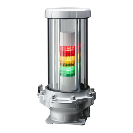
Explosion-proof Signal Tower
Designed by
ATEX certificate No. DEKRA 22ATEX0067 X
INSTRUCTION MANUAL
IECEx certificate No. IECEx DEK 22.0059X
Ex db B+H T6 Gb
2 G
Thank you very much for purchasing our PATLITE products.
Notice to Customer
● Request the installation and wiring be performed by a professional contractor if construction work is involved.
● Prior to installation, read this manual thoroughly before using this product to ensure correct use.
● If there are any questions concerning this product, refer to the information on the last page to ask your nearest Sales Representative.
● This product can be used in Zone 1 (Class I hazardous locations) and Zone 2 (Class II hazardous locations) where hydrogen gas is present.
● Use for warning purposes in places where there is a risk of ignition and explosion, such as gas facilities, painting lines, nuclear power plants, chemical plants, and steel plants.
● Applicable in environment with hydrogen and an explosive gas group II A and II B.
Notice to Installers
● Read this instruction manual carefully before installation, and install the product properly in accordance with the relevant regulations.
or Contractors
● Be sure to return this manual to the customer.
● Install the product securely in accordance with the relevant regulations (※) and this manual.
● For safety reasons, the installation of this product must be performed by two or more persons.
※Relevant regulations refer to IEC 60079-14 (Electrical apparatus for explosive gas atmospheres−Part 14 : Electrical installations in
hazardous areas (other than mines)).
●Applicable standards: IEC 60079-0 : 2017 (Ed. 7) and IEC 60079-1:2014 (Ed. 7), EN IEC 60079-0 : 2018 and EN IEC 60079-1 : 2014
The following is an explanation of the precautions that must be taken to prevent injury to the user or other persons or damage to property.
■The following symbols are used to classify and explain the degree of harm or damage that may occur if the product is used incorrectly and
the contents of the symbols are ignored.
Indicates an imminently dangerous condition:
Warning
failure to follow the instructions may lead to
death or serious injury.
1
Read this First (Safety Precautions)
Warning
Failure to observe the following may result in death or serious injury.
● In the event of a failure or malfunction with this product that could lead to serious accidents or impact human life or property,
take appropriate safety measures by using additional equipment as necessary.
● To prevent electric shock, short-circuits or damage, observe the following:
-Make sure to disconnect the power before construction work, replacement or repair, including the replacement of the fuse.
-Use this product in a properly maintained condition.
● Make sure that the product is disconnected from power source when opening and closing the cover of main body and bracket.
● Make sure to observe the specifications and environmental conditions specified in the specifications section.
Improper use of the product may result in an explosion if the surrounding gas reaches the ignition point.
-Use the product within the environmental conditions specified in the specifications section.
-Do not use in Zone 0 area (area where explosive atmosphere is present continuously for long periods of time or will frequently occur).
-Opening and closing the main unit cover from the bracket should be only performed by individuals trained in explosion-proof safety with
the supervisor's permission.
-Use cables for wiring that meet the specifications of the cable gland.
● If any deformation, cracks, or damage to the main cover or glass globe are found, stop using the product and contact your nearest Sales
representative.
● Do not open this product in areas where explosive atmospheres may be present.
● Do not open when an explosive atmosphere is present.
● Make sure to choose DC, AC and voltage correctly.
● Electrostatic charge may accumulate. Do not wipe the surface with a dry cloth.
● Since this product is heavy, select a location with a firm foothold or a solid mounting base for installation.
● Handle this product as a heavy object.
During transport and installation, take care not to drop the product and wear safety shoes and other protective gear.
● After installing this product, do not use it as a step to climb on or hang objects on it.
This may cause the product to tip over, fall or malfunction, and is very dangerous.
2
Accessory List
Main unit (1 piece)
・ Hexagonal wrench (1 piece) opposite side 8mm
・ This document (Instruction manual)
3
Model Number Configuration
Series
Rated Voltage
EDLR
-
302 F
3M2F
DC 24V
AC 100V-240V
Installation
Operation
Safety Precautions
Indicates a potentially dangerous condition:
Caution
failure to follow the instructions may lead to
slight injury or property damage.
LED Unit Color
RYG
E
-
-
R
Y
G
Red
Amber
Green
4
Part Names & Dimensions
GA0008960_03
Body cover
Maintenance
Glass globe
Lamp
(Signal Tower)
Hinge
Bracket
Nameplate
5
Installation & Wiring
● Installation and wiring must be performed by a specialist in accordance with IEC 60079-14.
● For safety reasons, the installation of this product must be performed by two or more persons.
● Make sure to turn off the power supply during the installation.
● When opening and closing the main unit cover, be careful not to damage the joint surfaces of the main unit cover
and bracket.
● Make sure to choose the correct voltage when wiring inside of the bracket.
● Do not apply voltage to the flashing common line (
the power line (
● Do not flash the light by turning the power ON and OFF repeatedly for (
● For wiring work, the appropriate size of the explosion-proof cable gland is NPT 3/4. Make sure the threaded
Caution
connection is properly sealed to prevent water penetration.
● Use the explosion-proof cable gland available from our optional parts (certified products). Explosion-proof cable
glands other than our optional parts cannot be used, as this is a requirement of the explosion-proof certification.
● When wiring the terminal block, do not apply excessive force. This may result in damage, deformation and
potential failure.
● To prevent twisting or disconnecting earthing connection facility, the earthing wire should be secured to fixed part.
● The stranded wire is suitable for connecting 0.75 to 2.5 mm² conductor.
● For the internal earthing connection facility, according to the size of the stranded wire used, the same conductor
size shall be selected and used from 0.75 to 2.5 mm².
● The external earthing connection facility is suitable for connecting 4 mm² wiring.
● About shat bolt between body cover and bracket, see specific condition of use.
■ Installation
1. Drill the mounting holes (refer to the mounting dimensions shown in "4. Part Names & Dimensions ") at the installation site.
2. Secure and fix the main unit at 4 points with M8 bolts and nuts. (Recommended tightening torque: 12.3 N m)
(M8 bolts and nuts are not included.)
■ Wiring
1. Remove the 8 hexagon socket head cap screws (M10 X 27) with the supplied hex wrench and open the space between the main unit cover
and the bracket. The main unit cover and bracket are connected by a hinge. Do not remove the hinge.
2. When connecting wires to terminal block (refer to P3. Terminal Block Wiring Procedure), make sure the polarity is correct.
3. Connect the ground wire to the external ground terminal or the ground terminal of the terminal block.
For connection to external ground terminal
For connection to the ground terminal of terminal block : Use wires between 0.75 mm
※For further specifications on wiring, refer to "Terminal Block Wiring Procedure".
4. Close the main unit cover and secure the unit firmly by tightening the 8 hex socket head cap screws (M10 X 27) using the supplied hexagonal
wrench. (Recommended tightening torque: 24.4 N m)
When doing so, be careful not to pinch the wires. Also, do not remove the O-ring (rubber gasket) that comes with the main unit cover.
<Space dimension required for wiring>
228
109
231
Hexagon socket head cap screw
8 places (M10 X 27)
External ground terminal
Wiring port
(Grounding terminal)
With round terminal
+Pan head screw (M4 X 8)
(Recommended tightening
torque 1.4 N ・ m)
□155
10.5
View A
), or to any lines (signal lines, common lines) other than
). This will result in malfunction.
: Use the supplied round terminals and 4 mm
Joint surface
(507)
( Unit : mm )
Mounting hole
4-∅9
130
<Mounting dimensional drawing>
NPT3/4
(R5.5-4)
<Detail drawing of View A>
). This may cause a malfunction.
wire.
2
and 2.5 mm
(φ1.1 to φ1.6).
2
2
Advertisement

Subscribe to Our Youtube Channel
Related Manuals for Patlite EDLR


Summary of Contents for Patlite EDLR
- Page 1 Operation Maintenance Ex db B+H T6 Gb Hexagon socket head cap screw Thank you very much for purchasing our PATLITE products. Glass globe Notice to Customer 8 places (M10 X 27) ● Request the installation and wiring be performed by a professional contractor if construction work is involved.
- Page 2 Flathead screwdriver *¹ Characteristics may vary from specifications. Power Supply / Earth wires: ∅1.1 to 1.6 (0.75 to 2.5mm Model EDLR-302F EDLR-3M2F Screwdriver's slot *² Other mounting position, please contact your Signal / Common wires: ∅1.1 to 1.6 (0.75 to 2.5mm...
Need help?
Do you have a question about the EDLR and is the answer not in the manual?
Questions and answers