Table of Contents
Advertisement
Quick Links
Download this manual
See also:
Operating Manual
Notice to Customer
Thank you very much for purchasing our PATLITE product.
●Request the installation and wiring be performed by a
professional contractor if construction work is
involved.
●Prior to installation, read this manual thoroughly
before using this product to ensure correct use.
●To find out more about operation method, visit our
companyʼs homepage (http://www.patlite.com) for
further details.
●After reviewing this manual, if there are any questions
regarding this product, please contact the nearest
PATLITE office listed on the back cover of this manual.
Notice to Contractor
●Read this manual carefully prior to installation.
●Be sure to return this manual to the customer.
ghv Vertriebs-GmbH | Am Schammacher Feld 47 | 85567 Grafing | Telefon + 49 80 92 81 89
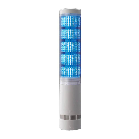
Signal Tower
L A 6
TYPE
INSTRUCTION MANUAL
[ Maintenance Version ]
Installation
Operation
1
Safety Precautions
2
Model Number
Configuration
3
Part Names and
Outer Appearance
4
How to Install
5
Wiring
6
Setup Data Transmission
Method
7
How to use
the "Setup Button"
8
Troubleshooting
9
Specifications
10
Replacement Parts
Maintenance
Page
16
17
18
20
22
24
25
25
26
27
15
Advertisement
Table of Contents

Related Manuals for Patlite REVOLITE LA6 Series


Summary of Contents for Patlite REVOLITE LA6 Series
- Page 1 Signal Tower L A 6 TYPE INSTRUCTION MANUAL [ Maintenance Version ] Installation Operation Maintenance Page Safety Precautions Model Number Configuration Part Names and Outer Appearance How to Install Wiring Notice to Customer Thank you very much for purchasing our PATLITE product. Setup Data Transmission ●Request the installation and wiring be performed by a Method professional contractor if construction work is involved. ●Prior to installation, read this manual thoroughly How to use before using this product to ensure correct use. the "Setup Button" ●To find out more about operation method, visit our companyʼs homepage (http://www.patlite.com) for further details. Troubleshooting ●After reviewing this manual, if there are any questions regarding this product, please contact the nearest PATLITE office listed on the back cover of this manual. Specifications Notice to Contractor ●Read this manual carefully prior to installation. ●Be sure to return this manual to the customer.
-
Page 2: Safety Precautions
Safety Precautions Safety Precautions Warning Failure to observe the following may result in death or serious injury. To prevent from short-circuits or To ensure safety when this product damage, observe the following: is installed onto equipment, observe the following. - Be sure the signal tower is disconnected from the power - Do not Use the signal tower as leverage when climbing up onto supply before wiring or performing repair work. the equipment. Failure to comply will result in falling from - Use the signal tower in a properly maintained condition. a high place, or damage to the product. (If parts such as the base or - When performing tasks such as outer cover lens are cracked, they should be repaired.) opening the covers of the equipment, be careful not to snag anything on the signal Request the installation and tower. Failure to comply will wiring be performed by a result in product damage. professional contractor if construction work is involved. Failure to comply may result in fire, electric shock or falling from high places may occur. Failure to comply with the following points may result in injury, Caution physical loss or damage. Avoid long exposure to the alarm ... -
Page 3: Model Number Configuration
Notice Do not operate this product This product is designed for use on a flat surface of a Type 1 Enclosure . without the waterproof packing (For UL Standard) material. Failure to comply will result in lower waterproofing performance. Type1 Enclosure By all means, do not apply voltage to the Flashing/Pulse The alarm sound is unidirectional, Flashing/Pulse Enable Common line. Enable Common line therefore it is most easily audible Failure to comply may result in in the direction from the source. malfunction. Position the signal tower so that ( Flashing/Alarm Specifications) the alarm sound is facing in the Do not connect power to the Flashing/Pulse desired sound direction. Flashing/Pulse Enable Common line. Enable Common line Power Supply (For Flashing/Alarm Specifications) Failure to comply may result in malfunction. Sound pressure may ( Flashing/Alarm Specifications) change in accordance to Use a "class 2" power supply the surrounding Class 2 specified in the guidelines under ... - Page 4 Part Names and Outer Appearance Outer Appearance List The full product appearance is indicated according to its model number. Refer to the model numbers as a reference to its appearance. Number of Lens Tiers lens tiers lens tiers Mounting/Wiring Installation Body Color Off-white Silver (Not available for the Specification.) Flashing/Alarm Option Part Names and Outer Appearance Each figure contains 5 lens tiers, with flashing and alarm functions. For 3 lens tiers, the outer lens height will be shorter. Also, for specifications not including the flashing/alarm functions, the product will not include a buzzer case. Direct mount Direct mount with Screwless Terminal ■ ■ (Unit:mm) with cable connection Block connection Spec. Underside View Threaded bore for cable gland attachment (M16×1.5 Effective screw length 12mm) <Spec.:Overall height> <Spec.:Overall height> - : 330 - : 320 - : 264 - : 254 - ...
- Page 5 ■ [ Steel pole with mounting angle and cable Number Name Material Number Name Material Head Cover Terminal Block Bracket ABS Lens PMMA Waterproof Packing Urethane Foam Outer lens Cable Body Pole Steel Pipe USB cover Mounting Angle Steel Plate <Spec.:Overall height> Buzzer case Setup Button - : 320 - : 254 Direct-mount Bracket ABS Accessory Assembly Steel - : 280 〈Note〉 The arrow mark (stackable mark) shows the part of the Main Unit - ...
-
Page 6: How To Install
How to Install Caution Use a soft cloth, etc., dampened The following requirements are with water to wipe the main signal necessary for proper installation. tower unit. (Do not use cleaners containing - Install the signal tower where chemicals such as those indicated below.) excessive vibration is not present. - Thinner - Install the signal tower on a - Benzine sturdy surface. - Gasoline - Install the signal tower on a level - Oil surface. Only install the signal tower in an This equipment has been tested upright or inverted position. and found to comply with the limits for a Class A digital device, pursuant to Part 15 of the FCC Rules. These limits are designed to provide reasonable protection against harmful interference when the equipment is operated Do not remove parts beyond those in a commercial environment. designed to be removed from this product. (Refer to Part Names and This product must not be used in residential areas. Dimensions" (P. 18) for parts which (Conformity requirements for CE Marking.) can be removed) General Installation Verify the signal tower installation position. Marking holes for wiring and installation. - Page 7 For Direct mount and cable model Thread the wires through the wiring hole. Insert a mounting bolt into the installation hole. Use waterproof sealing if needed. (→ (P.21) ) Point Attach the mounting nut from the back-side. 0.75 N . m (Standard) Recommended Torque For Direct Mount/Screwless Terminal Block model With the body ( type), or Assemble the body ( type) or alarm unit ( type), turn it to alarm unit ( type) is the right to remove. attached. 〈Notes〉 Do not pull the lead wire connected to the Terminal Attach the wires Block bracket and body (or (→ Wiring Example (P.22) ) alarm unit). Fix the Terminal Block Threaded bore for cable gland attachment bracket in place with a nut. (Effective Screw Length for M16x1.5 is 12 mm in length) 0.75 N . m (Standard) Recommended Torque ...
- Page 8 ( Direct Mount/ Screwless Terminal Block Specifications) Do not pull the lead wire or push Wire the product so that the lead it inside the body. wire does not protrude from the Screwless Terminal Block. Failure to comply may result in short-circuiting. ( Direct Mount/ Screwless Terminal Block Specifications) If wiring is extended beyond its factory length, Caution a relevance in the length of the wire and wire gauge that will cause a voltage drop. Wiring Example The wiring example indicates how to connect to external contacts for every classification. If there are any special applications that require asking questions concerning this product, feel free to contact your PATLITE Sales Representative. Wiring Example Index Screwless Terminal Block Connector PIN Arrangement ( Direct Mount/ Screwless Terminal Block Specifications) / ① LED Tier 1 / Input 1 PIN No. Function Name ( Direct Mount/ 9 10 11 [Signal Tower Mode] / [Smart Mode] Screwless Terminal Block Spec.) →Refer to the figure on the right "Screwless Terminal Block connector PIN arrangement." Lead Wire Color (Cable Specification) <Note> The lead wire color does not ...
- Page 9 Screwless Terminal Block wiring method ( Direct Mount/ Screwless Terminal Block Type) point The driver is removed to release ・The minus driver blade should be at least 2.5mm by 0.4mm the lever. (Check to make sure the lead wire has been locked in size. in place.) ・Do not forcibly push the lever more than necessary with the driver. Failure to comply may damage the unit. A minus driver etc. is used to pry the lever ・Strip 9mm (plus or minus 1mm) of wire insulation from the slot of the Terminal Block open, wire to insert it in the Terminal Block. by pushing straight onto the lever slot. ・When removing the lead wire, do not just pull to remove. Lever (Be sure to operate the lever to release the lock.) The stripped side of the lead wire is inserted in the slot. When an extra lead wire is not connected, it should be individually insulated with electrical tape or something similar. Caution 〈Note〉When lighting and flashing are used together in the Signal Tower mode with a PLC, it is necessary to separate the flashing and non-flashing circuit outputs on the PLC side. Do Not Apply Voltage! External Contact Classification Voltage Contact Relay For Flashing/ Pulse Enable External Contact Without flashing/alarm With flashing/alarm Flashing/Pulse Enable Common line / ⑨ Brown LED Tier 1 / Input 1 / ① LED Tier 2 / Input 2 / ...
- Page 10 24V DC Class2 (Ensure the USB cover is closed.) Micro USB Connector (Micro-B Female) Point If the power supply input to the product is set to ON, the "Settings" button in the software for creation of setup data can be clicked to test the setup data operation. ※To find out about the software for creation of setup data , visit our company's homepage (http://www.patlite.com) for further details. ghv Vertriebs-GmbH | Am Schammacher Feld 47 | 85567 Grafing | Telefon + 49 80 92 81 89...
-
Page 11: Troubleshooting
- Version Confirmation …… The current version of the product can be checked. - Product Initialization ……… The memory contents of the product can be cleared and returned to factory default values. (Returns to the Signal Tower setup mode. The alarm sound pattern and the "Smart Mode" setup data have not changed.) ■Setup Button Operation Method (Alarm Sound Control) Push Button Push Button Push Button Push Button Push Button Standard Mode Volume Volume Volume Mute Large Medium Small To find out more about operation methods other than "Alarm Sound Control", visit our company's homepage (http://www.patlite.com) for further details. Troubleshooting If a problem occurs, check the following table to remedy the problem before calling for service. Problem Where to Check Inspection Repair Refer to Wiring (->P.22, 23). to verify Is the electric wiring connected correctly? The LED does not wiring is correct. light up. Is the power properly supplying the correct voltage? Be sure to use 24VDC. A different LED tier Refer to Wiring (->P.22, 23). to verify Is the electric wiring connected correctly? from what I thought wiring is correct. lights up when I make it turn on. -
Page 12: Specifications
Specifications Specifications Model LA6-□D□□□-□ (Refer to "2. Model Number Configuration") Rated Voltage 24V DC Operating Voltage Range ±10% of Rated Voltage LA6-5D□□N-RYGBC LA6-5D□□B-RYGBC 6.5W Typ. Rated Power LA6-3D□□N-RYG 3.5W LA6-3D□□B-RYG 4.5W LA6-5D□□N-YYYYY LA6-5D□□B-YYYYY Consumption Max. LA6-3D□□N-YYY 4.5W LA6-3D□□B-YYY 5.5W Alarm Sound No.1 at Maximum Volume Environmental Condition Signal Wire Current Max. 70mA Standby Current Max. 15mA - 25℃ 〜 + 60℃ Operating Ambient Temperature Operating Ambient Humidity Less than 90% (No Dew or Condensation) Storage Ambient Temperature - 25℃ 〜 + 60℃ Storage Ambient Humidity Less than 90% (No Dew or Condensation) Mounting Location Indoor Only Upright Horizontal... -
Page 13: Replacement Parts
Replacement Parts The following replacement parts for this product are available. Head Cover USB Cover Waterproof Ring B x 2 Waterproof Ring B are 2pcs. The Head Cover is a single article. The USB Cover is a single article. Pole Bracket Terminal Block Bracket Direct-mount Bracket ( For with flashing/alarm type) The Direct-mount Bracket is Set of Pole Bracket, Pole Waterproof Ring a single article. and Screw(2pcs.). Pole Waterproof Ring The Terminal Block Bracket is a single article. Pole Waterproof Ring The is a single article. ghv Vertriebs-GmbH | Am Schammacher Feld 47 | 85567 Grafing | Telefon + 49 80 92 81 89... - Page 14 ghv Vertriebs-GmbH | Am Schammacher Feld 47 | 85567 Grafing | Telefon + 49 80 92 81 89...
- Page 15 取付型紙〔Installation Template〕 仕様の場合 注意 〔CAUTION〕 W J TN 〔For type〕 コピーして使用する場合や、 データからプリントアウトした場合は、 製品の取付ボルトや取付アングルと位置合わせするか、 寸法確認用 製品正面 〔Front of product〕 スケールを計測し、 実寸になっていることを確認してください! ※1 (ブザー開口部 〔Alarm output〕 ) 〔If using a copier machine, Ensure that it is actual size.〕 取付穴 〔Mounting Hole〕 ( 5) ∅ <寸法確認用スケール〔Scale for dimensions check〕 > 仕様の場合 製品外形 〔 type〕 〔Product outline〕 ∅ 取付穴 〔Mounting Hole〕 取付穴 ( 11) ∅ 〔Mounting Hole〕...
- Page 16 メモ Memo (取付型紙) 書込みなどしないでください。 (Installation template) Do not write here. ghv Vertriebs-GmbH | Am Schammacher Feld 47 | 85567 Grafing | Telefon + 49 80 92 81 89...
Need help?
Do you have a question about the REVOLITE LA6 Series and is the answer not in the manual?
Questions and answers