Table of Contents
Advertisement
Thank you very much for purchasing our PATLITE product.
Notice to Customer
●Request the installation and wiring be performed by a
professional contractor if construction work is involved.
●Prior to installation, read this manual thoroughly before
using this product to ensure correct use.
●After reviewing this manual, if there are any questions
regarding this product, please contact the nearest
PATLITE office listed on the back cover of this manual.
Notice to Contractor
●Read this manual carefully prior to installation.
●Be sure to return this manual to the customer.
ghv Vertriebs-GmbH | Am Schammacher Feld 47 | 85567 Grafing | Telefon + 49 80 92 81 89 0 | info@ghv.de | www.ghv.de
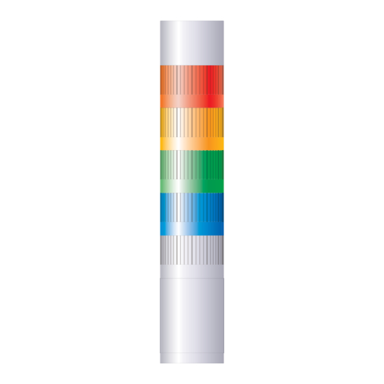
Signal Tower
L R 4 / L R 5 /
TYPE
L R 6 / L R 7
Complete Operation Manual
Installation
Operation
1
Safety Precautions
2
Model Number
Configuration
3
Part Names and
Outer Appearance
4
Installation
5
Wiring
6
Buzzer Pattern Set-up
7
How to use
the Folding Bracket
8
Unit Detachment
Method
9
Troubleshooting
10
Specifications
11
Replacement Parts
12
Optional Parts
1
B95100502_02
Maintenance
Page
2
3
7
19
23
33
34
35
50
51
55
57
Advertisement
Table of Contents


Need help?
Do you have a question about the LR4 and is the answer not in the manual?
Questions and answers