Table of Contents
Advertisement
Advertisement
Table of Contents
Troubleshooting

Related Manuals for Cisco Catalyst WS-C2924-XL


Summary of Contents for Cisco Catalyst WS-C2924-XL
- Page 1 Catalyst 2900 Series XL Hardware Installation Guide April 2002 Corporate Headquarters Cisco Systems, Inc. 170 West Tasman Drive San Jose, CA 95134-1706 http://www.cisco.com Tel: 408 526-4000 800 553-NETS (6387) Fax: 408 526-4100 Customer Order Number: DOC-786461= Text Part Number: 78-6461-04...
- Page 2 You can determine whether your equipment is causing interference by turning it off. If the interference stops, it was probably caused by the Cisco equipment or one of its peripheral devices. If the equipment causes interference to radio or television reception, try to correct the interference by using one or more of the following measures: •...
- Page 3 All other trademarks mentioned in this document or Web site are the property of their respective owners. The use of the word partner does not imply a partnership relationship between Cisco and any other company. (0201R) Catalyst 2900 Series XL Hardware Installation Guide Copyright ©...
-
Page 5: Table Of Contents
Documentation Feedback xviii Obtaining Technical Assistance xviii Cisco.com xviii Technical Assistance Center Contacting TAC by Using the Cisco TAC Website Contacting TAC by Telephone Product Overview C H A P T E R Features Management Interface Options Front-Panel Description 10/100 Ports... - Page 6 Module Slot LEDs 1-19 Rear-Panel Description 1-19 Power Connectors 1-21 Internal Power Supply Connector 1-21 DC Power Connector 1-21 Cisco RPS Connector 1-22 Console Port 1-23 Installation C H A P T E R Preparing for Installation Warnings EMC Regulatory Statements U.S.A.
- Page 7 Contents Mounting the Switch in a Rack 2-18 Attaching the Optional Cable Guide 2-19 Installing the Switch on a Wall 2-20 Attaching the Brackets to the Switch 2-21 Mounting the Switch to a Wall 2-22 Powering On the Switch and Running POST 2-24 Connecting to DC Power 2-25...
- Page 8 Console Port Identifying a Rollover Cable Connecting to a PC Connecting to a Terminal Translated Safety Warnings Attaching the Cisco RPS (model PWR600-AC-RPS) Attaching the Cisco RPS (model PWR300-AC-RPS-N1) Qualified Personnel Warning Installation Warning Jewelry Removal Warning Stacking the Chassis Warning...
- Page 9 Contents Class 1 Laser Product Warning C-22 Laser Beam Exposure Warning C-23 No On/Off Switch Warning C-24 Chassis Warning—Rack-Mounting and Servicing C-25 Reinforced Insulation Warning C-29 LAN Connections Only Warning C-30 No Field-Replaceable Units Warning C-31 Installation Warning C-32 SELV Source Warning C-33 Restricted Access Warning C-34...
- Page 10 Contents Catalyst 2900 Series XL Hardware Installation Guide 78-6461-04...
-
Page 11: Preface
Preface Audience This guide is for the networking or computer technician responsible for installing and configuring a Catalyst 2900 series XL switch. We assume that you are familiar with the concepts and terminology of Ethernet and local area networking. Purpose The Catalyst 2900 Series XL Hardware Installation Guide documents the hardware features of Catalyst 2900 series XL switches. -
Page 12: Conventions
Preface Conventions Appendix A, “Technical Specifications,” lists the physical and environmental specifications for the switches and the regulatory agency approvals. Appendix B, “Connectors and Cable Specifications,” describes the connectors, cables, and adapters that can be used to connect to the switch. Appendix C, “Translated Safety Warnings,”... - Page 13 Preface Conventions Warning This warning symbol means danger. You are in a situation that could cause bodily injury. Before you work on any equipment, be aware of the hazards involved with electrical circuitry and be familiar with standard practices for preventing accidents. (To see translations of the warnings that appear in this publication, refer to the Appendix C, “Translated Safety Warnings.”)
- Page 14 Preface Conventions Warnung Dieses Warnsymbol bedeutet Gefahr. Sie befinden sich in einer Situation, die zu einer Körperverletzung führen könnte. Bevor Sie mit der Arbeit an irgendeinem Gerät beginnen, seien Sie sich der mit elektrischen Stromkreisen verbundenen Gefahren und der Standardpraktiken zur Vermeidung von Unfällen bewußt. (Übersetzungen der in dieser Veröffentlichung enthaltenen Warnhinweise finden Sie im Anhang mit dem Titel C “Translated Safety Warnings”...
-
Page 15: Related Publications
These documents provide complete information about the switch and are available from the Cisco.com site: http://www.cisco.com/univercd/cc/td/doc/product/lan/c2900xl/index.htm You can order printed copies of documents with a DOC-xxxxxx= number from the Cisco.com sites and from the telephone numbers listed in the “Obtaining Documentation” section on page xvi. -
Page 16: Obtaining Documentation
Catalyst GigaStack Gigabit Interface Converter Hardware Installation Guide • (order number DOC-786460=) Cisco LRE CPE Hardware Installation Guide • (order number DOC-7811469=) Installation Notes for the Cisco LRE 48 POTS Splitter (order number • DOC-7812250=) • Installation Notes for Wall-Mount Brackets (order number DOC-7813035=) Obtaining Documentation The following sections provide sources for obtaining documentation from Cisco Systems. -
Page 17: World Wide Web
Preface Obtaining Documentation World Wide Web You can access the most current Cisco documentation on the World Wide Web at the following sites: http://www.cisco.com • • http://www-china.cisco.com http://www-europe.cisco.com • Cisco Documentation CD-ROM Cisco documentation and additional literature are available in a CD-ROM package, which ships with your product. -
Page 18: Documentation Feedback
Obtaining Technical Assistance Documentation Feedback If you are reading Cisco product documentation on the World Wide Web, you can send us your comments by completing the online survey. When you display the document listing for this platform, click Give Us Your Feedback. If you are using the product-specific CD and you are connected to the Internet, click the pencil-and-paper icon in the toolbar to display the survey. -
Page 19: Technical Assistance Center
P4—You need information or assistance on Cisco product capabilities, • product installation, or basic product configuration. In each of the above cases, use the Cisco TAC website to quickly find answers to your questions. To register for Cisco.com, go to the following website: http://www.cisco.com/register/... -
Page 20: Contacting Tac By Telephone
Preface Obtaining Technical Assistance If you cannot resolve your technical issue by using the TAC online resources, Cisco.com registered users can open a case online by using the TAC Case Open tool at the following website: http://www.cisco.com/tac/caseopen Contacting TAC by Telephone If you have a priority level 1 (P1) or priority level 2 (P2) problem, contact TAC by telephone and immediately open a case. -
Page 21: Product Overview
Features The switches are stackable 10/100 Ethernet switches to which you can connect workstations, Cisco IP Phones, and other network devices such as servers, routers, and other switches. The 2900 XL LRE switches employ Long-Reach Ethernet (LRE), a very-high-data-rate digital subscriber line (VDSL)-based technology that allows an Ethernet network to reach distances up to 4921 feet (1500 meters). - Page 22 On the Catalyst 2912 LRE XL and 2924 LRE XL switches, up to 24 LRE • ports through one RJ-21 connector and hot swapping capability with the Cisco LRE customer premises equipment (CPE) devices Supports up to 2048 MAC addresses on the Catalyst 2924 XL, 2924C XL, and •...
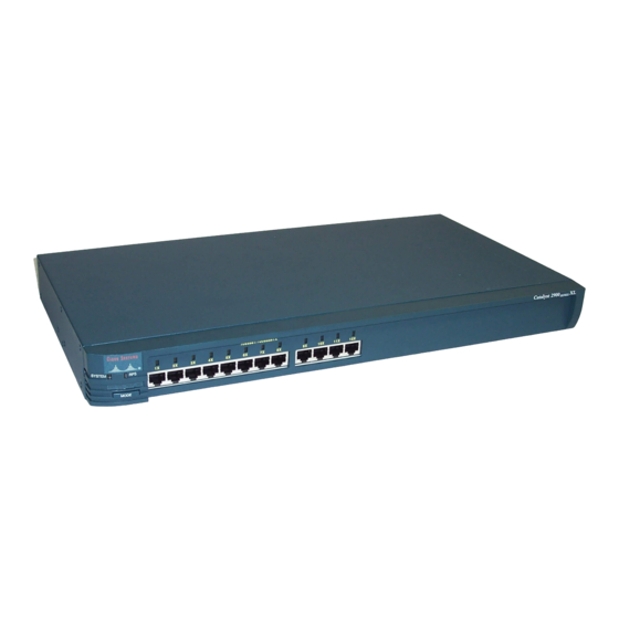
- Page 23 SER IES WS-C2924C-XL 22 fixed autosensing 10/100 ports 2 100BASE-FX ports 10BA SE-T /100B ASE- SER IES 100 BAS E-FX WS-C2924-XL 24 fixed autosensing 10/100 ports 10BA SE-T /100B ASE- 100B aseF SER IES WS-C2912MF-XL 12 100BASE-FX ports 2 expansion slots...
-
Page 24: Management Interface Options
Chapter 1 Product Overview Front-Panel Description Management Interface Options You can configure and monitor individual switches and switch clusters by using these interfaces: Cluster Management Suite (CMS)—CMS is a graphical user interface that • can be launched from anywhere in your network through a web browser such as Netscape Communicator or Microsoft Internet Explorer. - Page 25 Chapter 1 Product Overview Front-Panel Description Figure 1-2 Catalyst 2900 XL Front-Panel 10/100 Ports 10 BA SE -T/ 10 0B AS 10 0B as eF E-T X SE RI ES 10 0B AS E- FX 10/100 ports 100BASE-FX ports Figure 1-3 Catalyst 2900 XL 100BASE-FX ports and Module Slots Expansion slots SE RI ES...
-
Page 26: 10/100 Ports
The 10/100 ports on the Catalyst 2900 XL switches provide protocol support for Cisco IP Phones and per-port priority override. Refer to the Catalyst 2900 Series XL and Catalyst 3500 Series XL Software Configuration Guide for more information about these features. -
Page 27: 100Base-Fx Ports
Mbps (full duplex) and distances of up to 4921 feet (1500 meters). You can connect Cisco 575 LRE CPE and Cisco 585 LRE CPE devices to LRE ports on the same Catalyst 2900 LRE XL switch, and you can hot swap the CPE devices without powering down the switch or disrupting the other switch ports. -
Page 28: Module Slots
Product Overview Front-Panel Description (PSTN). For more information about the Cisco LRE 48 POTS Splitter (PS-1M-LRE-48), refer to the Installation Notes for the Cisco LRE 48 POTS Splitter. Cisco Long-Reach Ethernet (LRE) products are designed to share lines with Note analog, Integrated Services Digital Network (ISDN), and digital private branch exchange (PBX) switch telephones that use the 0 to 700 kHz frequency range. -
Page 29: Leds
Chapter 1 Product Overview Front-Panel Description Table 1-1 Expansion Modules (continued) Module Type Model Number 1000BASE-T WS-X2932-XL Ethernet Gigabit WS-X2931-XL WS-X2971-XL WS-X2972-XL WS-X2951-XL WS-X2961-XL 1. The Ethernet Gigabit module supports several Gigabit Interface Converter (GBIC) devices. For a complete list and the minimum software release required, refer to the Release Notes for the Catalyst 2900 Series XL and Catalyst 3500 Series XL Switches. - Page 30 Chapter 1 Product Overview Front-Panel Description All of the LEDs described in this section except the utilization meter (UTL) are visible on the Cluster Management Suite (CMS) window and, if the switch is a cluster member, on the CMS Cluster Manager window. The Catalyst 2900 Series XL and Catalyst 3500 Series XL Software Configuration Guide describes how to use CMS to manage standalone or individual switches and how to use cluster management software to manage switch clusters].
- Page 31 Chapter 1 Product Overview Front-Panel Description Figure 1-6 Catalyst 2912MF XL, 2924M XL, and 2924M XL DC LEDs 10BASE-FX port LEDs 1 0 0 B A S E -F X System LED RPS LED Expansion slot status LED Port mode LED Mode button Catalyst 2900 Series XL Hardware Installation Guide 1-11...
-
Page 32: System Led
Chapter 1 Product Overview Front-Panel Description Figure 1-7 Catalyst 2912 LRE XL and 2924 LRE XL LEDs 10/100 port LEDs S Y S T E M R P S M O D E L R E S T A T D U P L X S P E E D Mode... -
Page 33: Rps Led
Product Overview Front-Panel Description RPS LED The Catalyst 2912 LRE XL and Catalyst 2924 LRE XL switches use the Cisco RPS 300 (model PWR300-AC-RPS-N1). All other Catalyst 2900 XL and Catalyst 3500 XL switches use the Cisco RPS 600 (model PWR600-AC-RPS). -
Page 34: Port Leds And Modes
The RPS is in standby mode or in a fault condition. Press the Standby/Active button on the RPS, and the LED should turn green. If it does not, the RPS fan could have failed. Contact Cisco Systems. Blinking amber The internal power supply in a switch has failed, and the RPS is providing power to the switch (redundancy has been allocated to this device). - Page 35 Chapter 1 Product Overview Front-Panel Description Table 1-5 Port Mode LEDs on Catalyst 2912 LRE XL and 2924 LRE XL Switches Mode LED Port Mode Description LRE link status Long-Reach Ethernet (LRE) link status of the LRE ports on the Catalyst 2912 LRE XL and Catalyst 2924 LRE XL switches.
- Page 36 Chapter 1 Product Overview Front-Panel Description Table 1-6 Meanings of Port Status LED Colors for Different Modes on Catalyst 2912 XL, 2924C XL, 2924 XL, 2924MF XL, 2924M XL, and 2924M XL DC Switches Port Mode Port LED Color Meaning STAT No link.
- Page 37 Blinking amber Activity on the LRE port. Port is sending or receiving data, but it is not in STP forwarding state. DUPLX Cisco IOS Cisco IOS Release 12.0(5.x)WC4 Release 12.0(5.x)WC1/ Cyan (off) Cyan LRE port or remote CPE Ethernet port is operating in (off) half-duplex mode.
- Page 38 1. The LEDs on Catalyst 2900 LRE XL switches with Cisco IOS Release 12.0(5.x)WC1 or Cisco IOS Release 12.0(5.x)WC2 provide information about the connected Cisco 575 LRE CPE devices. These IOS releases do not support the Cisco 585 LRE CPE devices.
-
Page 39: Module Slot Leds
Chapter 1 Product Overview Rear-Panel Description Module Slot LEDs Module slot LEDs (shown in Figure 1-6) show the status of installed modules. The LEDs are numbered 1 (left slot) and 2 (right slot). Table 1-8 lists LED colors and their meanings. Table 1-8 Expansion Slot LEDs Color... - Page 40 Chapter 1 Product Overview Rear-Panel Description Figure 1-11 Catalyst 2912 LRE XL, and 2924 LRE XL Rear Panel 10 0- 24 0V ~ 5- 3A M AX IM UM 30 50 /6 0H 0W TO TA L OU TP UT DC OU TP UT AC power...
-
Page 41: Power Connectors
CO NN EC TI NG PO W ER D C IN PU The Cisco RPS does not support the Catalyst 2924M XL DC switch. Note Power Connectors You can provide power to the switch either through the internal power supply or through the Cisco RPS. -
Page 42: Cisco Rps Connector
DC output power modules. The power source is quasi-redundant because there are two AC input power modules for the Cisco RPS and one DC output power module for each external device. The AC input to the Cisco RPS is fully redundant, but the DC output to the external devices is not. -
Page 43: Console Port
Note same time, any subsequent switch is not supported by the RPS until the first switch failure is resolved. For more information on the Cisco RPS 300, refer to the Cisco Redundant Power System 300 Hardware Installation Guide. Console Port You can connect a switch to a PC through the switch console port and by using the supplied rollover cable and DB-9 adapter. - Page 44 Chapter 1 Product Overview Power Connectors Catalyst 2900 Series XL Hardware Installation Guide 1-24 78-6461-04...
-
Page 45: Installation
C H A P T E R Installation This chapter describes how to install your Catalyst 2900 XL switch and interpret the power-on self-test (POST) that ensures proper operation. Read the topics and perform these procedures in the order that they are presented: Pre-installation information and guidelines •... -
Page 46: Chapter 2 Installation
Chapter 2 Installation Preparing for Installation Only trained and qualified personnel should be allowed to install or replace this Warning equipment. Read the installation instructions before you connect the system to its power Warning source. Before working on equipment that is connected to power lines, remove jewelry Warning (including rings, necklaces, and watches). - Page 47 Chapter 2 Installation Preparing for Installation This product relies on the building’s installation for short-circuit (overcurrent) Warning protection. Ensure that a fuse or circuit breaker no larger than 120 VAC, 15A U.S. (240 VAC, 10A international) is used on the phase conductors (all current-carrying conductors).
-
Page 48: Emc Regulatory Statements
100BASE-FX single-mode supervisor engine module. Avoid exposure and do not stare into open apertures. Avoid exposure to the laser beam. Warning Attach only the Cisco RPS (model PWR600-AC-RPS) to the RPS receptacle. Warning Warning Attach only the Cisco RPS (model PWR300-AC-RPS-N1) to the RPS receptacle. -
Page 49: Japan
Chapter 2 Installation Preparing for Installation Japan This is a Class A product based on the standard of the Voluntary Control Council for Interference by Information Technology Equipment (VCCI). If this equipment is used in a domestic environment, radio disturbance may arise. When such trouble occurs, the user may be required to take corrective actions. -
Page 50: Hungary
Chapter 2 Installation Preparing for Installation Hungary This equipment is a Class A product and should be used and installed properly according to the Hungarian EMC Class A requirements (MSZEN55022). Class A equipment is designed for typical commercial establishments for which special conditions of installation and protection distance are used. -
Page 51: Verifying Package Contents
Carefully remove the contents from the shipping container, and check each item Note for damage. If any item is missing or damaged, contact your Cisco representative or reseller for support. Return all packing materials to the shipping container and save them. - Page 52 The cable guide does not attach to the Catalyst 2912 LRE XL and Note 2924 LRE XL switches. One RJ-45-to-DB-9 adapter • Cisco Information Packet, containing warranty, safety, and support • information In addition to these items, the Catalyst 2924M XL DC switch also ships with a Note DC terminal block plug on the switch back panel.
-
Page 53: Installing The Switch On A Table Or Shelf
Chapter 2 Installation Installing the Switch on a Table or Shelf Installing the Switch on a Table or Shelf Follow these steps to install the switch on a table or shelf: Locate the adhesive strip with the rubber feet in the mounting-kit envelope. Step 1 Attach the four rubber feet to the recessed areas on the bottom of the unit. - Page 54 Chapter 2 Installation Installing the Switch in a Rack Figure 2-1 Mounting Bracket Points for Catalyst 2912 XL, 2924C XL, 2924 XL, 2912MF XL, 2924M XL, and 2924M XL DC Switches 19" rack 24" rack 23" rack mount point mount point mount point 19"...
-
Page 55: Removing Screws From The Switch
Chapter 2 Installation Installing the Switch in a Rack “Attaching the Brackets to a Catalyst 2912 LRE XL or 2924 LRE XL Switch” • section on page 2-16 “Mounting the Switch in a Rack” section on page 2-18 • • “Attaching the Optional Cable Guide”... - Page 56 Chapter 2 Installation Installing the Switch in a Rack For a 19-inch or a telco rack, use the supplied Phillips flat-head screws to • attach the long side of the bracket to the switch. For a 23- or 24-inch rack, use the supplied Phillips truss-head screws to attach •...
- Page 57 Chapter 2 Installation Installing the Switch in a Rack Figure 2-5 Attaching Brackets on Catalyst 2912MF XL, 2924M XL, and 2924M XL DC Modular Switches (Front-Panel Forward) Phillips flat-head screws 19" configuration Phillips truss-head screws 23" and 24" configuration Catalyst 2900 Series XL Hardware Installation Guide 2-13 78-6461-04...
- Page 58 Chapter 2 Installation Installing the Switch in a Rack Figure 2-6 Attaching Brackets on Catalyst 2912 XL, 2924C XL, and 2924 XL Fixed-Port Switches (Rear-Panel Forward) Phillips flat-head screws 19" configuration Phillips truss-head screws 23" and 24" configuration Catalyst 2900 Series XL Hardware Installation Guide 2-14 78-6461-04...
- Page 59 Chapter 2 Installation Installing the Switch in a Rack Figure 2-7 Attaching Brackets on Catalyst 2912MF XL, 2924M XL, and 2924M XL DC Modular Switches (Rear-Panel Forward) Phillips flat-head RA TI NG screws 10 0- 12 0/ 20 0- 24 2.
- Page 60 Chapter 2 Installation Installing the Switch in a Rack Attaching the Brackets to a Catalyst 2912 LRE XL or 2924 LRE XL Switch A Catalyst 2912 LRE XL or 2924 LRE XL switch can only be rack-mounted in a 19-inch rack. To attach the brackets to a Catalyst 2912 LRE XL or 2924 LRE XL switch, use the supplied Phillips flat-head screws to attach the long side of the bracket to the switch.
- Page 61 Chapter 2 Installation Installing the Switch in a Rack Figure 2-9 Attaching Brackets on Catalyst 2912 LRE XL and 2924 LRE XL Switches (Front-Panel Forward) Phillips flat-head screws IN P U T P W R O U T P U T P W R R E S E T T E M P...
-
Page 62: Mounting The Switch In A Rack
Chapter 2 Installation Installing the Switch in a Rack Figure 2-10 Attaching Brackets on Catalyst 2912 LRE XL and 2924 LRE XL Switches (Rear-Panel Forward Phillips flat-head screws 19" configuration Phillips truss-head screws 23" and 24" configuration Mounting the Switch in a Rack After the brackets are attached to the switch, use the four supplied number-12 Phillips machine screws to securely attach the brackets to the rack, as shown in Figure... -
Page 63: Attaching The Optional Cable Guide
Chapter 2 Installation Installing the Switch in a Rack Figure 2-11 Mounting the Switch in a Rack 10 Ba se T/1 10 Ba se T/1 10 0B as eF 00 Ba se TX 00 Ba se TX SE RI ES Phillips machine screws SE RI ES... -
Page 64: Installing The Switch On A Wall
Chapter 2 Installation Installing the Switch on a Wall The cable guide does not attach to the Catalyst 2912 LRE XL and 2924 LRE XL Note switches. Figure 2-12 Attaching the Cable Guide 10 Ba se T/1 10 Ba se T/1 10 0B as eF 00 Ba se TX 00 Ba se TX... -
Page 65: Attaching The Brackets To The Switch
Installing the Switch on a Wall To mount a Catalyst 2912 LRE XL or 2924 LRE XL switch on a Note wall, you need to obtain two special wall-mount brackets (Cisco part number wallmount-1ru=.) To order these brackets, contact your Cisco sales representative. -
Page 66: Mounting The Switch To A Wall
Chapter 2 Installation Installing the Switch on a Wall Figure 2-14 Attaching Brackets for Parallel and Vertical Wall-Mounting for Modular Switches RA TI NG 10 0- 12 0/ 20 0- 24 2. 0A /1 .0 A 50 -6 0H Z D C IN PU Phillips truss-head... - Page 67 Chapter 2 Installation Installing the Switch on a Wall Figure 2-15 Mounting a Fixed-Port Switch to a Wall Vertical wall stud User-supplied screws Catalyst 2900 Series XL Hardware Installation Guide 2-23 78-6461-04...
-
Page 68: Powering On The Switch And Running Post
Chapter 2 Installation Powering On the Switch and Running POST Figure 2-16 Mounting a Modular Switch to a Wall Vertical wall stud User-supplied screws User-supplied screws Vertical wall-mount Parallel wall-mount After the switch is mounted on the wall, power the switch as described in “Powering On the Switch and Running POST”... -
Page 69: Connecting To Dc Power
Chapter 3, “Troubleshooting,” to determine a course of action. POST failures are usually fatal. Call Cisco Systems immediately if your switch does not pass POST. Connecting to DC Power To connect the Catalyst 2924M XL DC switch to a DC-input power source, follow... -
Page 70: Grounding The Switch
Chapter 2 Installation Connecting to DC Power Four leads of 12- or 14-gauge copper wire • • Wire-stripping tool(s) for stripping both 6- and 12- or 14-gauge wires Grounding the Switch This equipment is intended to be grounded. Ensure that the host is connected to Warning earth ground during normal use. - Page 71 Chapter 2 Installation Connecting to DC Power Figure 2-17 Removing the Ground-Lug Screws C O N SO IN PU T: 36 - 72 CU RR EN T: 4- RE FE R TO M AN BE FO RE UA L CO NN EC TI NG PO W ER D C IN PU...
- Page 72 Chapter 2 Installation Connecting to DC Power Figure 2-19 Crimping the Ground Lug Use the two number-10-16 screws to attach the ground lug and wire assembly to Step 6 the rear panel of the switch. Using a ratcheting torque screwdriver, torque each ground-lug screw to 15 1bf-in. Step 7 (or 240 ounce-force inches [240 ozf-in.]).
-
Page 73: Wiring The Dc-Input Power Source
Chapter 2 Installation Connecting to DC Power Figure 2-20 Torquing Ground-Lug Screws C O N SO IN PU T: 36 - 72 CU RR EN T: 4- RE FE R TO M AN BE FO RE UA L CO NN EC TI NG PO W ER D C IN PU... - Page 74 Chapter 2 Installation Connecting to DC Power The switch is to be installed with 5A-branch-circuit protection. Caution This installation must comply with all applicable codes. Note Follow these steps for wiring the switch to a DC-input power source: Locate and remove the terminal block plug. It is already in the DC power Step 1 connector on the switch back panel.
- Page 75 Chapter 2 Installation Connecting to DC Power Figure 2-22 Positive and Negative Positions on the Switch Rear Panel C O N SO IN PU T: 36 - 72 CU RR EN T: 4- RE FE R TO M AN BE FO RE UA L CO NN EC TI NG...
- Page 76 Chapter 2 Installation Connecting to DC Power Figure 2-24 Inserting Wires into the Terminal Block Plug Return Feed A Negative Return Feed B Negative Use a ratcheting torque screwdriver to torque the terminal block captive screw Step 5 (above the installed wire lead) to 4.5 1bf-in. (72 ozf-in.). (See Figure 2-25.) Do not overtorque the terminal-block captive screws.
- Page 77 Chapter 2 Installation Connecting to DC Power Figure 2-25 Torquing the Terminal-Block Captive Screws Torque to 4.5 lbf-in. (72 ozf-in.) Repeat Steps 4 and 5 for the remaining three DC-input power source wires. Step 6 Figure 2-26 shows the completed wiring of a terminal block plug. Catalyst 2900 Series XL Hardware Installation Guide 2-33 78-6461-04...
- Page 78 Chapter 2 Installation Connecting to DC Power Figure 2-26 Completed Wiring of Terminal Block Plug Return Feed A Negative Return Feed B Negative Step 7 Insert the terminal block plug into the terminal block header on the rear panel of the switch.
-
Page 79: Connecting To A 10/100 Port
Set the port speed and duplex parameters on both ends of the connection. Follow these steps to connect to 10BASE-T and 100BASE-TX devices: When connecting to workstations, servers, routers, and Cisco IP Phones, connect Step 1 a straight-through Category 5 cable to an RJ-45 connector on the front panel (Figure 2-28). - Page 80 The switch can connect to a Cisco IP Phone through a straight-through, Note twisted-pair cable. The rear panel of the Cisco IP Phone might have more than one RJ-45 jack. Use the LAN-to-phone jack to connect the telephone to the switch. Refer to the documentation that came with your Cisco IP Phone for information about connecting devices to it.
-
Page 81: Connecting To A 100Base-Fx Port
Chapter 2 Installation Connecting to a 100BASE-FX Port Connecting to a 100BASE-FX Port Invisible laser radiation may be emitted from the aperture ports of the Warning 100BASE-FX single-mode supervisor engine module. Avoid exposure and do not stare into open apertures. Warning Avoid exposure to the laser beam. -
Page 82: Connecting To An Lre Port
Depending on the switch model, you can connect the LRE port to either 12 or 24 LRE customer premises equipment (CPE) devices through a patch panel. You can connect both Cisco 575 LRE CPE and Cisco 585 LRE CPE devices to Note your LRE switch, and you can hot swap the CPE devices without powering down the switch or disrupting the other switch ports. - Page 83 Connecting the LRE port to a patch panel or POTS splitter requires a male-to-male RJ-21 cable, Category 3 or above. You can order RJ-21 cables from your cable vendor, or you can order these cables from your Cisco sales representative: CAB-5-M120M120-5= (Category 5 cable with 90-degree, male-to-male •...
- Page 84 Chapter 2 Installation Connecting to an LRE Port Figure 2-30 Connecting to an LRE Port RJ-21 connector S Y S T E M R P S M O D E LR E S T A T D U P LX S P E E D Screw RJ-21...
- Page 85 Connect the other end of the cable to the patch panel or POTS splitter. Step 3 Each LRE port status LED turns on when it establishes a link with a Cisco LRE CPE. For more information about the LRE link between the switch LRE port and...
-
Page 86: Connecting To A Module Port
You need to provide a RJ-45-to-DB-25 female DTE adapter if you want to connect the switch console port to a terminal. You can order a kit (part number ACS-DSBUASYN=) containing that adapter from Cisco. For console port and adapter pinout information, see the “Cable and Adapter... -
Page 87: Where To Go Next
IP information on the switch. For information about using the setup program, refer to the Release Notes for the Catalyst 2900 Series XL and Catalyst 3500 Series XL Cisco IOS Release 12.0(5)WC(1). For information about configuring the switch, refer to the Catalyst 2900 Series XL and Catalyst 3500 Series XL Software Configuration Guide. - Page 88 Chapter 2 Installation Where to Go Next Catalyst 2900 Series XL Hardware Installation Guide 2-44 78-6461-04...
-
Page 89: Troubleshooting
C H A P T E R Troubleshooting The LEDs on the front panel of the Catalyst 2900 series XL switch provide troubleshooting information about the switch. They show failures in the power-on self-test (POST), port-connectivity problems, and overall switch performance. For a full description of the switch LEDs, see the “LEDs”... -
Page 90: Chapter 3 Troubleshooting
If a test fails, the port status LED associated with the test turns amber, and the system LED turns amber. Table 3-1 lists the eight tests and their associated LEDs. POST failures are usually fatal. Call Cisco Systems if your switch does not pass Note POST. -
Page 91: Diagnosing Problems
Chapter 3 Troubleshooting Diagnosing Problems Diagnosing Problems Common switch problems fall into the following categories: Poor performance • No connectivity • Corrupted software • Table 3-2 describes how to detect and resolve these problems. Catalyst 2900 Series XL Hardware Installation Guide 78-6461-04... -
Page 92: Diagnosing Problems
Chapter 3 Troubleshooting Diagnosing Problems Table 3-2 Common Problems and Their Solutions Symptom Possible Cause Resolution Poor Performance or Duplex autonegotiation mismatch. Refer to the Catalyst 2900 Series Excessive Errors. XL and Catalyst 3500 Series XL Software Configuration Guide for information on identifying autonegotiation mismatches. - Page 93 Replace telephone cable. Cable trunking defective. Repair cable trunking or select an alternative pair. Cisco LRE CPE not communicating with Verify switch and upstream or might be attempting to exceed rate or network status. reach selected by the Catalyst 2900 LRE XL switch.
- Page 94 Chapter 3 Troubleshooting Diagnosing Problems Table 3-2 Common Problems and Their Solutions (continued) Symptom Possible Cause Resolution LRE status LED not turned RJ-21 cable loose or not connected Reseat RJ-21 connector and fasten properly. with screw or cable tie. Trunk cable defective. Test trunk cable.
- Page 95 Consider use of appropriate • services in bundle. public profile in bundles shared with other services. Restrict the use of spectrally • incompatible services. Local nonstandard noise source. Consult Cisco sales representative for installation optimization. Catalyst 2900 Series XL Hardware Installation Guide 78-6461-04...
- Page 96 PHONE socket on LRE CPE off-hook, placed on-hook, device. rings, or dials. Terminate additional • telephone lines with microfilters. For more information about microfilters, contact your Cisco sales representative. Catalyst 2900 Series XL Hardware Installation Guide 78-6461-04...
- Page 97 Chapter 3 Troubleshooting Diagnosing Problems Table 3-2 Common Problems and Their Solutions (continued) Symptom Possible Cause Resolution Ethernet performance Interleaver introduces extra latency to Adjust upper-layer network • degradation due to increase noise margin. protocols to allow for high excessive network latency.
- Page 98 Chapter 3 Troubleshooting Diagnosing Problems Catalyst 2900 Series XL Hardware Installation Guide 3-10 78-6461-04...
- Page 99 A P P E N D I X Technical Specifications Table A-1, Table A-2, Table A-3, and Table A-5 list the technical specifications for the Catalyst 2900 series switches. For switches that support modules (Catalyst 2912MF XL and 2924M XL), also refer to the Catalyst 2900 Series XL Modules Installation Guide and the Catalyst 2900 Series XL ATM Modules Installation Guide for additional specifications.
- Page 100 Appendix A Technical Specifications Table A-1 Technical Specifications for the Catalyst 2912 XL and Catalyst 2912MF XL Switches Catalyst 2912 XL Catalyst 2912MF XL Environmental Ranges Operating temperature 32 to 113°F (0 to 45°C) 32 to 113°F (0 to 45°C) Storage temperature –4 to 149°F (–10 to 65°C) –4 to 149°F (–10 to 65°C)
-
Page 101: Technical Specifications
Appendix A Technical Specifications Table A-2 Technical Specifications for the Catalyst 2924 XL and Catalyst 2924C XL Switches Catalyst 2924 XL Catalyst 2924C XL Environmental Operating Ranges Operating temperature 32 to 113°F (0 to 45°C) 32 to 113°F (0 to 45°C) Storage temperature –4 to 149°F (–10 to 65°C) –4 to 149°F (–10 to 65°C) - Page 102 Appendix A Technical Specifications Table A-3 Technical Specifications for the Catalyst 2924M XL Switches Environmental Operating Ranges Operating temperature 32 to 113°F (0 to 45°C) Storage temperature –4 to 149°F (–10 to 65°C) Operating humidity 10 to 85% (noncondensing) Operating altitude Up to 10,000 ft (3000 m) Storage altitude Up to 15,000 ft (4570 m)
- Page 103 Appendix A Technical Specifications Table A-4 Technical Specifications for Catalyst 2924M XL DC Switches Environmental Ranges Operating temperature 32 to 113°F (0 to 45°C) Storage temperature –4 to 149°F (–10 to 65°C) Operating humidity 10 to 85% (noncondensing) Operating altitude Up to 10,000 ft (3000 m) Storage altitude Up to 15,000 ft (4570 m)
- Page 104 Appendix A Technical Specifications Table A-5 Technical Specifications for the Catalyst 2912 LRE XL and 2924 LRE XL Switches (continued) AC input voltage 100 to 127/200 to 240 VAC (autoranging) 50 to 60 Hz DC input voltages +12V @12A Power consumption Physical Dimensions Weight •...
-
Page 105: Connectors And Cable Specifications
A P P E N D I X Connectors and Cable Specifications This appendix describes the Catalyst 2900 XL switch ports and the cables and adapters that you use to connect the switch to other devices. Connector Specifications 10/100 Ports The 10/100 Ethernet ports use standard RJ-45 connectors and Ethernet pinouts with internal crossovers, as shown by an X in the port name. -
Page 106: 100Base-Fx Ports
10/100 Port Pinouts Label 4 5 6 7 8 When connecting the 10/100 ports to compatible workstations, servers, routers, and Cisco IP Phones, you must use a straight-through cable wired for 10BASE-T and 100BASE-TX. (Figure B-5 shows the straight-through cable schematics.) When connecting to other switches or repeaters, you must use a crossover cable. -
Page 107: Lre Ports
Appendix B Connectors and Cable Specifications Connector Specifications Figure B-2 100BASE-FX SC Connector LRE Ports The LRE ports use a single RJ-21 connector, as shown in Figure B-3. Figure B-3 RJ-21 Connector S Y S T E M R P S M O D E LR E S T A T... -
Page 108: Cable And Adapter Specifications
Appendix B Connectors and Cable Specifications Cable and Adapter Specifications port to a terminal. You can order a kit (part number ACS-DSBUASYN=) containing that adapter from Cisco. For console port and adapter pinout information, see Table B-2 Table B-4. Cable and Adapter Specifications... -
Page 109: Rj-21 Cable Pinouts
Appendix B Connectors and Cable Specifications Cable and Adapter Specifications RJ-21 Cable Pinouts Table B-1 RJ-21 Cable Pinouts Pins Circuit Pins Circuits 1, 26 1, tip/ring 14, 39 14, tip/ring 2, 27 2, tip/ring 15, 40 15, tip/ring 3, 28 3, tip/ring 16, 41 16, tip/ring... -
Page 110: Identifying A Rollover Cable
Appendix B Connectors and Cable Specifications Identifying a Rollover Cable Identifying a Rollover Cable You can identify a rollover cable by comparing the two modular ends of the cable. Hold the cable ends side-by-side, with the tab at the back. The wire connected to the pin on the outside of the left plug should be the same color as the wire connected to the pin on the outside of the right plug (see Figure... -
Page 111: Connecting To A Terminal
RJ-45-to-RJ-45 rollover cable, and the RJ-45-to-DB-25 female DTE adapter. The RJ-45-to-DB-25 female DTE adapter is not supplied with the switch. You can Note order a kit (part number ACS-DSBUASYN=) containing this adapter from Cisco. Catalyst 2900 Series XL Hardware Installation Guide 78-6461-04... - Page 112 Appendix B Connectors and Cable Specifications Identifying a Rollover Cable Table B-3 Console Port Signaling and Cabling Using a DB-25 Adapter Console RJ-45-to-RJ-45 RJ-45-to-DB-25 Console Port (DTE) Rollover Cable Terminal Adapter Device Signal RJ-45 Pin RJ-45 Pin DB-25 Pin Signal Not connected Not connected Console Port Signaling and Cabling Using a DB-25 Adapter...
-
Page 113: Translated Safety Warnings
This warning applies to the Catalyst 2912 XL, 2924 XL, 2924C XL, 2924M XL, and switches 2924C XL Warning Attach only the Cisco RPS (model PWR600-AC-RPS) to the RPS receptacle. Waarschuwing: Slechts de Cisco RPS (model PWR600-AC-RPS) aan de RPS contactdoos verbinden. Varoitus Kiinnitä... -
Page 114: Attaching The Cisco Rps (Model Pwr300-Ac-Rps-N1
Attaching the Cisco RPS (model PWR300-AC-RPS-N1) Advarsel! Koble bare Cisco RPS (modell PWR600-AC-RPS) til RPS-stikkontakten. Aviso Anexe o RPS Cisco (modelo PWR600-AC-RPS) apenas ao receptáculo RPS. Aviso: Sólo conecte el Cisco RPS (modelo PWR600-AC-RPS) al receptáculo RPS. Varning! Koppla endast Ciscos RPS (modell PWR600-AC-RPS) till RPS-uttaget. -
Page 115: Qualified Personnel Warning
Chapter C Translated Safety Warnings Qualified Personnel Warning Aviso Anexe o RPS Cisco (modelo PWR300-AC-RPS-N1) apenas ao receptáculo RPS. Aviso: Sólo conecte el Cisco RPS (modelo PWR300-AC-RPS-N1) al receptáculo RPS. Varning! Koppla endast Ciscos RPS (modell PWR300-AC-RPS-N1) till RPS-uttaget. Qualified Personnel Warning... -
Page 116: Installation Warning
Chapter C Translated Safety Warnings Installation Warning ¡Atención! Estos equipos deben ser instalados y reemplazados exclusivamente por personal técnico adecuadamente preparado y capacitado. Varning Denna utrustning ska endast installeras och bytas ut av utbildad och kvalificerad personal. Installation Warning Warning Read the installation instructions before you connect the system to its power source. -
Page 117: Jewelry Removal Warning
Chapter C Translated Safety Warnings Jewelry Removal Warning ¡Advertencia! Ver las instrucciones de instalación antes de conectar el sistema a la red de alimentación. Varning! Läs installationsanvisningarna innan du kopplar systemet till dess strömförsörjningsenhet. Jewelry Removal Warning Before working on equipment that is connected to power lines, remove Warning jewelry (including rings, necklaces, and watches). - Page 118 Chapter C Translated Safety Warnings Jewelry Removal Warning Warnung Vor der Arbeit an Geräten, die an das Netz angeschlossen sind, jeglichen Schmuck (einschließlich Ringe, Ketten und Uhren) abnehmen. Metallgegenstände erhitzen sich, wenn sie an das Netz und die Erde angeschlossen werden, und können schwere Verbrennungen verursachen oder an die Anschlußklemmen angeschweißt werden.
-
Page 119: Stacking The Chassis Warning
Chapter C Translated Safety Warnings Stacking the Chassis Warning Stacking the Chassis Warning Do not stack the chassis on any other equipment. If the chassis falls, it can Warning cause severe bodily injury and equipment damage. Waarschuwing Het chassis mag niet op andere apparatuur gestapeld te worden. Als het chassis mocht vallen, kan dit ernstig lichamelijk letsel en beschadiging van de apparatuur veroorzaken. -
Page 120: Main Disconnecting Device
Chapter C Translated Safety Warnings Main Disconnecting Device Main Disconnecting Device The plug-socket combination must be accessible at all times because it Warning serves as the main disconnecting device. Waarschuwing De combinatie van de stekker en het elektrisch contactpunt moet te allen tijde toegankelijk zijn omdat deze het hoofdmechanisme vormt voor verbreking van de aansluiting. -
Page 121: Overtemperature Warning
Chapter C Translated Safety Warnings Overtemperature Warning Overtemperature Warning To prevent the switch from overheating, do not operate it in an area that Warning exceeds the maximum recommended ambient temperature of 104°F (40°C). To prevent airflow restriction, allow at least 3 inches (7.6 cm) of clearance around the ventilation openings. -
Page 122: Tn Power Warning
Chapter C Translated Safety Warnings TN Power Warning Advarsel For å unngå at bryteren overopphetes skal utstyret ikke brukes på steder hvor anbefalt maks omgivelsestemperatur overstiger 104 grader Farenheit (40°C). La det være minst 3 tommer (7,6 cm) klaring rundt ventilasjonsåpningene for at luftsirkulasjonen skal være uhindret. -
Page 123: Ground Connection Warning
Chapter C Translated Safety Warnings Ground Connection Warning Avvertenza Il dispositivo è stato progettato per l’uso con sistemi di alimentazione TN. Advarsel Utstyret er utfomet til bruk med TN-strømsystemer. Aviso O dispositivo foi criado para operar com sistemas de corrente TN. ¡Advertencia! El equipo está... -
Page 124: Circuit Breaker (15A) Warning
Chapter C Translated Safety Warnings Circuit Breaker (15A) Warning Aviso Ao instalar a unidade, a ligação à terra deverá ser sempre a primeira a ser ligada, e a última a ser desligada. ¡Advertencia! Al instalar el equipo, conectar la tierra la primera y desconectarla la última. - Page 125 Chapter C Translated Safety Warnings Circuit Breaker (15A) Warning Warnung Dieses Produkt ist darauf angewiesen, daß im Gebäude ein Kurzschluß- bzw. Überstromschutz installiert ist. Stellen Sie sicher, daß eine Sicherung oder ein Unterbrecher von nicht mehr als 240 V Wechselstrom, 16 A (bzw. in den USA 120 V Wechselstrom, 15 A) an den Phasenleitern (allen stromführenden Leitern) verwendet wird.
-
Page 126: Grounded Equipment Warning
Chapter C Translated Safety Warnings Grounded Equipment Warning Grounded Equipment Warning This equipment is intended to be grounded. Ensure that the host is connected Warning to earth ground during normal use. Waarschuwing Deze apparatuur hoort geaard te worden Zorg dat de host-computer tijdens normaal gebruik met aarde is verbonden. -
Page 127: Supply Circuit Warning
Chapter C Translated Safety Warnings Supply Circuit Warning Supply Circuit Warning Care must be given to connecting units to the supply circuit so that wiring is Warning not overloaded. Waarschuwing Let erop dat de toestellen op voedingscircuits worden aangesloten zonder het vermogen van de bedrading te overschrijden. -
Page 128: Voltage Warning
Chapter C Translated Safety Warnings Voltage Warning ¡Atención! Poner mucho cuidado al conectar los equipos al circuito de alimentación a fin de no sobrecargar el cableado. Varning Var noga vid anslutning av enheter till matarströmkretsen så att ledningarna inte överbelastas. Voltage Warning Warning A voltage mismatch can cause equipment damage and may pose a fire hazard. -
Page 129: Power Supply Warning
Chapter C Translated Safety Warnings Power Supply Warning Advarsel Ulik spenning kan forårsake skade på utstyret og innebære brannfare. Dersom spenningen på merkelappen er forskjellig fra spenningen i stikkontakten, må du ikke koble kabinettet til den stikkontakten. Aviso Uma voltagem incorrecta poderá causar danos no equipamento e constituir um risco de incêndio. - Page 130 Chapter C Translated Safety Warnings Power Supply Warning Varoitus Älä kosketa virtalähdettä virtajohdon ollessa kytkettynä. Virrankatkaisimella varustetuissa järjestelmissä on virtalähteen sisällä jäljellä verkkojännite, vaikka virrankatkaisin on katkaistu-asennossa virtajohdon ollessa kytkettynä. Järjestelmissä, joissa ei ole virrankatkaisinta, on virtalähteen sisällä verkkojännite, kun virtajohto on kytkettynä.
-
Page 131: Lightning Activity Warning
Chapter C Translated Safety Warnings Lightning Activity Warning Aviso Não toque na unidade abastecedora de energia quando o cabo de alimentação estiver ligado. Em sistemas com interruptor, a corrente eléctrica estará presente na unidade abastecedora, sempre que o cabo de alimentação de energia estiver ligado, mesmo quando o interruptor se encontrar desligado. - Page 132 Chapter C Translated Safety Warnings Lightning Activity Warning Varoitus Älä työskentele järjestelmän parissa äläkä yhdistä tai irrota kaapeleita ukkosilmalla. Attention Ne pas travailler sur le système ni brancher ou débrancher les câbles pendant un orage. Warnung Arbeiten Sie nicht am System und schließen Sie keine Kabel an bzw. trennen Sie keine ab, wenn es gewittert.
-
Page 133: Product Disposal Warning
Chapter C Translated Safety Warnings Product Disposal Warning Product Disposal Warning Ultimate disposal of this product should be handled according to all national Warning laws and regulations. Waarschuwing Het uiteindelijke wegruimen van dit product dient te geschieden in overeenstemming met alle nationale wetten en reglementen. Varoitus Tämä... -
Page 134: Class 1 Laser Product Warning
Chapter C Translated Safety Warnings Class 1 Laser Product Warning Class 1 Laser Product Warning Invisible laser radiation may be emitted from the aperture ports of the Warning 100BASE-FX single-mode supervisor engine module. Avoid exposure and do not stare into open apertures. Waarschuwing: Onzichtbare laserstralen kunnen uit de openingspoorten van de 100BASE-FX enkelkanaals supervisor motormodule komen. -
Page 135: Laser Beam Exposure Warning
Chapter C Translated Safety Warnings Laser Beam Exposure Warning Aviso: Los puertos de apertura del módulo de procesador de supervisión de modo único 100BASE-FX pueden emitir radiación láser invisible. Evite exponerse a la misma y no mire directamente a las aperturas. Varning! Osynlig laserstrålning kan eventuellt avges från öppningsportarna på... -
Page 136: No On/Off Switch Warning
Chapter C Translated Safety Warnings No On/Off Switch Warning No On/Off Switch Warning Unplug the power cord before you work on a system that does not have an Warning on/off switch. Waarschuwing Voordat u aan een systeem werkt dat geen aan/uit schakelaar heeft, dient u de stekker van het netsnoer uit het stopcontact te halen. -
Page 137: Chassis Warning-Rack-Mounting And Servicing
Chapter C Translated Safety Warnings Chassis Warning—Rack-Mounting and Servicing Chassis Warning—Rack-Mounting and Servicing To prevent bodily injury when mounting or servicing this unit in a Warning rack, you must take special precautions to ensure that the system remains stable. The following guidelines are provided to ensure your safety: This unit should be mounted at the bottom of the rack if it is the only unit in •... - Page 138 Chapter C Translated Safety Warnings Chassis Warning—Rack-Mounting and Servicing Varoitus Kun laite asetetaan telineeseen tai huolletaan sen ollessa telineessä, on noudatettava erityisiä varotoimia järjestelmän vakavuuden säilyttämiseksi, jotta vältytään loukkaantumiselta. Noudata seuraavia turvallisuusohjeita: Jos telineessä ei ole muita laitteita, aseta laite telineen alaosaan. •...
- Page 139 Chapter C Translated Safety Warnings Chassis Warning—Rack-Mounting and Servicing Avvertenza Per evitare infortuni fisici durante il montaggio o la manutenzione di questa unità in un supporto, occorre osservare speciali precauzioni per garantire che il sistema rimanga stabile. Le seguenti direttive vengono fornite per garantire la sicurezza personale: Questa unità...
- Page 140 Chapter C Translated Safety Warnings Chassis Warning—Rack-Mounting and Servicing Aviso Para se prevenir contra danos corporais ao montar ou reparar esta unidade numa estante, deverá tomar precauções especiais para se certificar de que o sistema possui um suporte estável. As seguintes directrizes ajudá-lo-ão a efectuar o seu trabalho com segurança: Esta unidade deverá...
-
Page 141: Reinforced Insulation Warning
Chapter C Translated Safety Warnings Reinforced Insulation Warning Reinforced Insulation Warning The customer 48V power system must provide reinforced Warning insulation between the primary AC power and the 48-VDC output. Waarschuwing Het 48 volt stroomsysteem van de klant dient versterkte isolatie tussen de primaire wisselstroom en de 48 VDC-uitgang te verschaffen. -
Page 142: Lan Connections Only Warning
Chapter C Translated Safety Warnings LAN Connections Only Warning LAN Connections Only Warning The Catalyst 2924M XL DC switch is intended for Local Area Warning Network (LAN) connections only. This unit is not certified for use in Public Telephone Networks. Waarschuwing De Catalyst 2924M XL DC schakelaar is alleen bestemd voor LAN-verbindingen. -
Page 143: No Field-Replaceable Units Warning
(FRUs). Do not open the chassis or attempt to remove or replace any components. For information about obtaining service for this unit, contact your reseller or Cisco sales representative. Waarschuwing De Catalyst 2924M XL DC bevat geen FRU's (field-replaceable units ofwel veldvervangbare eenheden). -
Page 144: Installation Warning
(Field-Replaceable Units, FRU). No abra el chasis ni intente reemplazar componentes. Para más información sobre cómo reparar este aparato, póngase en contacto con su distribuidor o representante de Cisco. Varning! Catalyst 2924M XL DC innehåller inte några enheter som kan bytas ut på... -
Page 145: Selv Source Warning
Chapter C Translated Safety Warnings SELV Source Warning Varoitus Lue asennusohjeet ennen järjestelmän yhdistämistä virtalähteeseen. Attention Avant de brancher le système sur la source d'alimentation, consulter les directives d'installation. Lesen Sie die Installationsanweisungen, bevor Sie das System an die Warnung Stromquelle anschließen. -
Page 146: Restricted Access Warning
Chapter C Translated Safety Warnings Restricted Access Warning Varoitus Liitä laite yhteen erittäin alhaisen jännitteen (SELV) lähteeseen. Attention Cet équipement doit être connecté à une alimentation SELV (Single Extra-Low Voltage). Schließen Sie das Gerät an eine einzelne Stromquelle mit Niedrigspannung Warnung (extra-low voltage - SELV) an. -
Page 147: Shielded Ethernet Cables Warning
Chapter C Translated Safety Warnings Shielded Ethernet Cables Warning Warnung Die Ausrüstung muß in einem Bereich installiert werden, der gegen unbefugtes Betreten geschützt ist. Avvertenza Installate questo apparato unicamente in zone di accesso regolamentate. Utstyret skal installeres på et sted med begrenset adgang. Advarsel Aviso O equipamento é... -
Page 148: Grounded Equipment Warning
Chapter C Translated Safety Warnings Grounded Equipment Warning Advarsel Ethernet-kabler skal være skjermet når de brukes i et sentralt kontormiljø. Aviso Os cabos “Ethernet” deverão estar armados quando usados em ambiente de escritório central. Los cables Ethernet deben estar protegidos cuando se usen dentro de una ¡Advertencia! oficina central. -
Page 149: Ground Connection Warning
Chapter C Translated Safety Warnings Ground Connection Warning Aviso Este equipamento deverá estar ligado à terra. Certifique-se que o host se encontra ligado à terra durante a sua utilização normal. ¡Advertencia! Este equipo debe conectarse a tierra. Asegurarse de que el equipo principal esté... -
Page 150: Qualified Personnel Warning
Chapter C Translated Safety Warnings Qualified Personnel Warning Advarsel Når enheten installeres, må jordledningen alltid tilkobles først og frakobles sist. Aviso Ao instalar a unidade, a ligação à terra deverá ser sempre a primeira a ser ligada, e a última a ser desligada. ¡Advertencia! Al instalar el equipo, conectar la tierra la primera y desconectarla la última. -
Page 151: Dc Power Disconnection Warning
Chapter C Translated Safety Warnings DC Power Disconnection Warning Aviso Este equipamento deverá ser instalado ou substituído apenas por pessoal devidamente treinado e qualificado. ¡Atención! Estos equipos deben ser instalados y reemplazados exclusivamente por personal técnico adecuadamente preparado y capacitado. Varning Denna utrustning ska endast installeras och bytas ut av utbildad och kvalificerad personal. - Page 152 Chapter C Translated Safety Warnings DC Power Disconnection Warning Attention Avant de pratiquer l'une quelconque des procédures ci-dessous, vérifier que le circuit en courant continu n'est plus sous tension. Pour en être sûr, localiser le disjoncteur situé sur le panneau de service du circuit en courant continu, placer le disjoncteur en position fermée (OFF) et, à...
-
Page 153: Exposed Wire Lead Warning
Chapter C Translated Safety Warnings Exposed Wire Lead Warning ¡Advertencia! Antes de proceder con los siguientes pasos, comprobar que la alimentación del circuito de corriente continua (CC) esté cortada (OFF). Para asegurarse de que toda la alimentación esté cortada (OFF), localizar el interruptor automático en el panel que alimenta al circuito de corriente continua, cambiar el interruptor automático a la posición de Apagado (OFF), y sujetar con cinta la palanca del interruptor automático en posición de Apagado... - Page 154 Chapter C Translated Safety Warnings Exposed Wire Lead Warning Warnung Eine ungeschützte Kabelleitung von einer Gleichstrom-Eingangsspannungsquelle kann schädliche Elektrizitätslevel führen. Achten Sie darauf, daß von dem Klemmleistenstecker aus kein ungeschütztes Eingangsgleichstromkabel freiliegt. Avvertenza Un cavo elettrico scoperto proveniente da un alimentatore DC-INPUT può trasmettere scariche elettriche ad elevata tensione.
-
Page 155: I N D E X
19-, 23-, and 24-inch racks RJ-21 pinouts rollover rollover pinouts DB-25 adapter AC power connecting to 2-24 See Cisco.com connector 1-21 chassis, warning against stacking warning C-1 to C-4 circuit breaker (15A) warning C-12 Catalyst 2900 Series XL Hardware Installation Guide... - Page 156 Index Cisco.com connectors and cables xviii 1-21 Cisco RPS 10/100BASE-T ports B-1 to B-2 See RPS 100BASE-FX ports 1-7, B-2 CiscoWorks 2000 console port 2-42 to 2-43 Class 1 laser product warning power (AC and RPS) C-22 1-21 RJ-21 connector...
- Page 157 1-19 10/100BASE-T ports supported modules 1-16 exposed wire lead warning C-41 port mode 1-16 hot-swappable modules HP OpenView feedback to Cisco Systems, web xviii fiber-optic cable 50/125- or 62.5/125-micron 2-37, B-2 installation front panel attaching mounting brackets 10/100 ports (rack-mount)
- Page 158 Index console port interpreting 1-14 connecting to 2-42 to 2-43 1-15 electrical noise, avoiding port (Catalyst 2900 LRE XL) 1-17 guidelines port status 1-9, 1-16 to 1-18 mounting in a rack POST results 2-18 to 2-19 2-24, 3-1 mounting on a wall 2-22 to 2-24 1-13 to 1-14 packing list...
- Page 159 Index mid-mount port LEDs See installation Catalyst 2900 LRE XL 1-17 attaching mounting brackets (telco ports rack-mount) 10/100BASE-T modules 100BASE-FX mounting brackets console 1-23 attaching 2-11, 2-15, 2-22 console connector pinouts LED colors 1-16 to 1-18 module no on/off switch warning C-24 port status LEDs 1-9, 1-16 to 1-18...
- Page 160 Index rack installation safety bracket mounting points SC connectors 2-10 rear panel SPEED LED 1-15 AC power connector stacking the chassis warning 1-21 console port STAT LED 1-14 to 1-17 RPS connector straight-through cable pinouts 1-21 regulatory statements, EMC cables 2-4 to 2-6 RJ-21 connector straight-through...
- Page 161 Index RJ-45-to-DB-25 RJ-45-to-DB-9 terminal emulation software 2-42 TN power warning C-10 translated warnings C-1 to C-28 UTL LED 1-14, 1-16 VDSL defined very-high-data-rate digital subscriber line See VDSL voltage warning C-16 warnings defined xiii to xv translated C-1 to C-28 Catalyst 2900 Series XL Hardware Installation Guide IN-7 78-6461-04...
- Page 162 Index Catalyst 2900 Series XL Hardware Installation Guide IN-8 78-6461-04...
Need help?
Do you have a question about the Catalyst WS-C2924-XL and is the answer not in the manual?
Questions and answers