Table of Contents
Advertisement
Quick Links
Installation and Operation Manual (AU/NZ)
Console Appliances - Front
Console Appliances Front Series:
Console Appliance 75 Front (decorative base optional)
Console Appliance 110 Front (decorative base optional)
Console Appliance 150 Front
Installation Manual (AU): Console Appliances-Front Series (V1.1)
Advertisement
Table of Contents

Related Manuals for ORTAL AGA Console Appliances Front Series


Summary of Contents for ORTAL AGA Console Appliances Front Series
- Page 1 Installation and Operation Manual (AU/NZ) Console Appliances - Front Console Appliances Front Series: Console Appliance 75 Front (decorative base optional) Console Appliance 110 Front (decorative base optional) Console Appliance 150 Front Installation Manual (AU): Console Appliances-Front Series (V1.1)
-
Page 2: General
This section provides safety guidelines and instructions. It is important to SAVE THESE INSTRUCTIONS and to make yourself fully aware of all the safety protocols and the many features of the ORTAL direct Flue gas fireplace appliance. INSTALLER: Please read this manual carefully before installation or use, and leave this manual with the customer for storage in a safe place for future reference. -
Page 3: General Fitting Information
WARNING –IF YOU SMELL GAS If you smell gas, take the following action immediately: Do not try to light any appliance. Do not touch any electrical switch. Do not use any phone in your building. Call your gas supplier from a neighbour’s phone, and follow the gas supplier’s instructions. ... -
Page 4: Table Of Contents
Pairing the Remote and Receiver Wiring Diagrams Interior Design Media Media Placement Guidelines Log Media Placement Arrangement of pebbles Arrangement of crystals Operation 10-Button Remote Control Handset Wall Switch Fireplace Maintenance General Maintenance Appendix A: ORTAL Factory Recommended Service Checklist... -
Page 5: Product Information
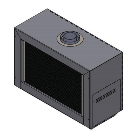
150 Front (co-axial) NOTES: Flueing is not supplied by Ortal with the fireplace. The fireplace is certified to be used with, and can be obtained from, the chimney manufacturers outlined in “General Flueing Requirements” section. General Product Information The Console Appliance Front series can be wall-mounted (standard option) or mounted to a decorative base supplied by Ortal (add- on feature). - Page 6 General Product Features Decorative Base (optional add-on)
-
Page 7: Product Dimensions
Product Dimensions Console Appliance 75 Front Approximate Weight: 78 kg... - Page 8 Hanging Bracket Console Appliance 75 Front with Decorative Base NOTE: The decorative base is an optional add-on feature available for the Console Appliance 75 Front and Console Appliance 110 Front. It allows the fireplace to be mounted to the base instead of a wall.
- Page 9 Console Appliance 110 Front Approximate Weight: 105 kg...
- Page 10 Hanging Bracket Console Appliance 110 Front with Decorative Base NOTE: The decorative base is an optional add-on feature available for the Console Appliance 75 Front and Console Appliance 110 Front. It allows the fireplace to be mounted to the base instead of a wall.
- Page 11 Console Appliance 150 Front Approximate Weight: 128 kg...
- Page 12 Hanging Bracket NOTE: The decorative base is not available for the Console Appliance 150 Front.
-
Page 13: Installation
Mount the fireplace at the desired location: On a wall (see “ Wall-Mounting Instructions” section on page 14 for details). On the Ortal decorative base (see “ Base-Mounting Instructions” section on page 22 for details). If fireplace is wall-mounted, remove shipping legs after installation. -
Page 14: Wall-Mounting Instructions
Wall-Mounting Instructions The following sections explain how to mount the fireplace on either (1) wood-framed walls or (2) concrete/masonry walls. The diagrams in these sections are for illustration purposes only and apply to all models covered in this manual. For clearances, see “Wall-Mounted Fireplace Clearances” section on page 30. NOTE: Wall framing and mounting hardware (not provided) must be able to support the weight of the fireplace: ... - Page 15 Locate the Hanging Bracket: Using the dimensions in the table and diagram below, measure down from the centre top your non-combustible zone. This is the centre line for the bolts for the hanging bracket. X Measurement: Console Appliance 75 Front: X = 52 cm Console Appliance 110 Front: X = 52 cm Console Appliance 150 Front: X = 52 cm DIAGRAM NOTE: The hanging bracket is shown in the diagram above as a reference point only.
- Page 16 Fill in Non-Combustible Zone: Fill and secure the entire non-combustible zone with 9 mm cement board, fireplace construction board (e.g., Skamotec 225), or its equivalent, matching the thickness of the surrounding wall. This board will likely need to be oversized so it can be attached to framing studs. Dimension will very per project. Drywall not permitted within the non-combustible zone.
- Page 17 Mount the Hanging Bracket: Centre the hanging bracket along the line marking you just made. Using the information in the table below, mount the bracket to the wall using the four 13 mm-diameter lag bolts following the bolt manufacturer's requirements (bolts are not provided). Recommended bolt length is minimum 75 mm but may need to be longer depending on project design needs.
- Page 18 Step 5: Mount the Fireplace to the Wall Recommended – Make a Vertical Mark on the Wall: Find the centre of the top of the hanging bracket and make a vertical mark at a 90º angle to the hanging bracket. This will be used as a guide to centre the fireplace while attaching it to the hanging bracket.
- Page 19 Concrete or Masonry Wall You will need to provide: Four 10 mm diameter extension bolts (recommended bolt length is minimum 75 mm but may need to be longer depending on project design needs) NOTE: This section assumes the non-combustible finish is already in place. Step 1: Mark the desired location of the fireplace on the wall.
- Page 20 NOTE: To ensure the fireplace can be installed tightly to the wall, make sure the bolt does not stick out more than 13 mm from the wall. Step 3: Mark the location of the gas line and electrical outlet on the wall. Find the Gas and Electrical Locations on the Wall: Route the gas line and outlet to the bottom right of the fireplace (in reference to a front view of the fireplace) using the hanging bracket marking made in Step 2.
- Page 21 Step 4: Mount the Fireplace to the Wall Recommended – Make a Vertical Mark on the Wall: Find the centre of the hanging bracket and make a vertical mark at a 90º angle to the hanging bracket. This will be used as a guide to centre the fireplace while attaching it to the hanging bracket. The mark will need to extend high enough to be seen while hanging the fireplace to the wall.
-
Page 22: Base-Mounting Instructions
Base-Mounting Instructions This section explains how to attach the fireplace to the Ortal Decorative Base. The fireplace does not need to be mounted to a wall if it is attached to this base. The base fully supports the entire weight of the fireplace. -
Page 29: Third Trip To Site: Start-Up
In addition, the installer must review and explain the following to the owner: Safety warnings Fireplace operation Warranty requirements Maintenance requirements Glass is hot during and after operation. If any questions or concerns arise, owner must contact the local Ortal dealer/installer for support. -
Page 30: Clearances
Clearances Wall-Mounted Fireplace Clearances Keep the following areas clear to specified materials: 25 mm clearance around the Flue pipe to any material. 300 mm clearance directly above the fireplace to any material. This does not apply to the wall behind the fireplace and extending upward. -
Page 31: Base-Mounted Fireplace Clearances
Base-Mounted Fireplace Clearances Keep the following areas clear to specified materials: 2.5 cm clearance around the flue pipe to any material. 2.5 cm clearance from the back of the fireplace to any material. 10 cm clearance directly above the fireplace to any material. This does not apply to the wall behind the fireplace and extending upward. -
Page 32: Decorative Skirt Installation
Decorative Skirt Installation NOTE: To remove the skirt, perform the steps below in reverse order. -
Page 33: Flueing
POWER FLUE NOTE: Console Appliance model fireplaces are approved for power-flueing with an Enervex system only. Ortal-manufactured power flues cannot be used with Console Appliance fireplaces. See Ortal’s Enervex RS Power Flue Manual for more details on power Flueing with an Enervex Power Flue. -
Page 34: Flue Configurations
The following sections provide information for calculating fue configuration distances and elbows. For flue configurations that cannot conform to these guidelines, consider the Enervex RS Power Flue System, or contact Ortal for assistance. Power Flue information can be found in the Ortal Enervex RS Power Flue System Manual. -
Page 35: Maximum Allowable Horizontal Runs
TERMINATION CAP NOTE: Low Profile Termination Cap and Sconce Termination Cap can negatively affect flame appearance and are not recommended for use with the fireplace. Maximum Allowable Horizontal Runs Console Appliance 75 Front Console Appliance 110 Front Console Appliance 150 Front V minimum = 0 metre V minimum = 90 cm V minimum = 90 cm... -
Page 36: Flue Restrictors
Flue Restrictors The restrictor sizing tables in this section determine the recommended restrictor for your flue configuration. These tables show Ortal’s recommendations only. The environment, gas type, and other factors may affect the best restrictor choice. How to use the “Recommended Restrictor” tables: Find the total vertical rise in your flue configuration along the y-axis. - Page 37 Restrictor Table: Console Appliance 110 V (m) Values in mm H (m) Restrictor Table: Console Appliance 150 V (m) Values in mm H (m)
-
Page 38: Flue Clearances
Flue Clearances The following clearances apply to the flue system regardless of flue manufacturer. Flue Clearances Sides: Applies to entire circumference when flueing is 25 mm oriented vertically. Clearance is to any material. *Top: 75 Applies to flueing oriented horizontally or at an angle. -
Page 39: Flue Termination
Flue Termination Horizontal Termination Clearances Location Minimum Clearance Description Clearance above grade, veranda, porch, deck, or balcony. 30 cm NOTE: On private property where termination is less than 18 cm above a sidewalk, driveway, deck, porch, veranda, or balcony, use of a listed cap shield is suggested. 30 cm Clearance to an operable window or door. - Page 40 Covered Alcove: spaces open only on one side and with an overhang Horizontal Termination Clearances Continued: Covered Alcove Application Location Country Minimum Clearance Description Clearance under non-vinyl veranda, porch, deck, balcony, or overhang. NOTE: Termination in a covered alcove space is permitted with the dimensions specified. 1.
-
Page 41: Vertical Termination Clearances
Vertical Termination Clearances Notes: 1. Maintain a minimum of 60 cm clearance between edge of vertical termination and perpendicular wall. 2. If terminating near window, keep minimum of 60 cm clearance between window and flue termination. 3. All mechanical air intakes (such as Fan exhaust) within 90 cm of a termination cap must be a minimum of 90 cm below the termination cap. -
Page 42: Chimney Shroud
Chimney Shroud Top Open Keep a minimum 15 cm clearance around the diameter of the cap’s side edge and extending above and below the cap. Sides Open Keep a minimum 15 cm clearance around the diameter of the cap’s side edge, and a minimum 25 cm clearance above the top of the cap. -
Page 43: Gas
The fireplaces are approved for use with natural gas (NG) or propane (LP) only. No other fuel types are permitted. Gas Pressures Model Console Appliance 75 Console Appliance 110 Burner Size Marked 650: Marked 220: Marked 1200: Marked 260: Injectors with 7x0.950mm with 7x0.550mm with 7x1.275mm... -
Page 44: Routing The Gas Line
Routing the Gas Line The fireplace gas and electrical components are located on the right side of the fireplace (in reference to a front view of the fireplace). Route the gas line and outlet (optional) to the bottom right of the fireplace). Refer to the table below for measurements. Correctly size and route the gas supply line to the back bottom side of the fireplace as shown in the figure and table below. -
Page 45: Gas Conversion
Gas conversion (NG to LP or LP to NG) of the Console Appliance series fireplaces can be done in the field. Gas conversion must only be performed by a technician who has specific authorization by Ortal to change these components. The conversion kit must be supplied by Ortal. -
Page 46: Gas And Electrical Components
Pilot Base Connection fitting 4mm One-piece Thermocouple NG Fitting for main line inlet to gas valve GV60 Thermocouple LPG The manufacturer of Ortal’s gas and electrical components is Mertik Maxitrol. For information on these components, please visit the manufacturer’s website: www.mertikmaxitrol.com... -
Page 47: Electrical
Electrical WARNING: Disconnect the power supply before servicing any electrical components. Electrical Requirements The Console Appliance Front series fireplaces have the option to run either on 4 AA batteries or a 6-Volt AC Adapter. The AC Adapter is provided with the fireplace. Batteries are not included. Batteries Four AA batteries (not provided) must be installed in the electrical receiver. -
Page 48: Pairing The Remote And Receiver
Pairing the Remote and Receiver To set up the remote-control device to operate the fireplace, follow the following guidelines to pair the remote and receiver unit on the same radio frequency. Press and hold the receiver’s reset button until you hear two beeps. The first beep is short, and the second beep is long. - Page 49 Wiring Diagram: Screen Fireplace (AC Adapter)
- Page 50 Home Automation Wiring Diagram Use the following wiring diagram to connect fireplace control a hardwired home automation system. Contacts Options/Operation Ignition: Close contacts 0 (orange) and 2 (brown) simultaneously for 1 second. Fireplace automatically goes to high after ignition. Up Flame: Close contacts 0 (orange) and 1 (red) simultaneously. The contact needs to be closed for 12 seconds to turn the motor from end-stop to end-stop.
-
Page 51: Interior Design Media
Interior Design Media ORTAL offers media such as logs and stones, that can be provided with the fireplace unit. This section provides guidelines for safe placement of media. WARNINGS –INSTALLING AND HANDLING MEDIA DO NOT install the interior design media until appliance installation is complete, the gas line is connected and tested for leaks, and initial burner operation has been inspected and approved. -
Page 52: Media Placement Guidelines
Media Placement Guidelines Follow the tips below for proper log media placement. Place the logs carefully to block as few ports as possible. Log Media Placement Logs must be placed in order and preset into location pins as shown: Figure 1: Log Media Placement for Clear 75 H F/RS/LS/TS/TU/SC, 170 H F/RS/LS/TS/TU Figure 2: Log Media Placement for Clear 110 H F/RS/LS/TS/TU/SC, 170 H F/RS/LS/TS/TU ... -
Page 53: Arrangement Of Pebbles
Figure 3: Log Media Placement for Clear 150 H F/RS/LS/TS/TU/SC, 170 H F/RS/LS/TS/TU Figure 4: Log Media Placement for Clear 200 H F/RS/LS/TS/TU/SC, Clear 200 F/RS/LS/TS/TU/SC Arrangement of pebbles Pebble arrangement for burner 45 Pebble arrangement for burners 100, 135 and 160 Do not place pebbles on the burner holes. -
Page 54: Arrangement Of Crystals
Arrangement of crystals Crystal arrangement for burner 45 Crystal arrangement for burners 100, 135 and 160 Do not place crystals on the burner holes. Arrange crystals only around the burner holes. -
Page 55: Operation
Operation WARNING – Read these instructions carefully before lighting the fireplace. Four operation options are available for use with the fireplace: 10-Button Remote Control Handset (default option, always included with the fireplace) Puck Handset (optional accessory) Wall Switch (optional accessory) ... -
Page 56: Wall Switch
Turning the Fireplace On 1. Press the button until you hear continuous beeping, and a blinking series of lines confirms the start sequence has begun; release buttons. 2. Main gas flows once pilot ignition is confirmed. 3. The system automatically goes into Manual Mode after main burner ignition. NOTE: When pilot ignition is confirmed, motor turns automatically to maximum flame height. - Page 57 Operating Instructions Turning the Fireplace On/Off ON: Press and hold the ON-OFF button until two short beeps confirms the start sequence has begun; release button. OFF: Press the ON-OFF button. Flame Height Adjustment INCREASE: To increase flame height, press and hold (up flame) button.
-
Page 58: Fireplace Maintenance
Submerged Parts Do not use the fireplace if any part has been under water, or if you suspect that it may have been under water. The Ortal dealer service technician must inspect and, if necessary, replace any parts of the control system and any gas controls which have been under water. -
Page 59: Appendix A: Ortal Factory Recommended Service Checklist
Model Type: Serial #: Date: Before, during and after service, if there is any doubt, stop and call ORTAL. If there is any NO answer, close the gas valve and correct. If you cannot correct, discontinue operation, lockout unit and call ORTAL. -
Page 60: Appendix B: Warranty Policy
ORTAL Product Service Log Appendix B: Warranty Policy Below is the warranty policy of Ortal Ltd for Standard products sold and distributed in Australia & New Zealand. Warranties may vary for custom models. THE WARRANTY The Ortal Ltd. Limited Warranty warrants your Ortal gas fireplace (“Product”) to be free from defects in materials and workmanship at the time of manufacture. - Page 61 Ortal will, at its option, repair or replace the covered components. If repair or replacement is not commercially practical, Ortal will, at its option, refund the purchase price or wholesale price of the Ortal product, whichever is applicable. Ortal will also pay Ortal prevailing labour rates, as determined in its sole discretion, incurred in repairing or replacing such components for up to 2 years.
-
Page 62: Manufacturer Contact Information
Submission of a completed warranty claim is the preferred method of warranty claim notification. Ortal must be notified of the claimed defect in writing within 90 days of the date of failure. Notices should be directed to the Ortal Warranty Department or visit our website at www.ortalheat.com/... - Page 63 © Ortal 2023 Version 1.2, July 2023 SKU: KPMANSAFRAU1.2 ORTAL HEADQUARTERS 14 Harash St. Neve Ne’eman, Hod HaSharon, 4524087, Israel Tel: +972-9-7402828 | Fax: +972-9-7402687 info@ortal-heat.com | www.ortalheat.com...
Need help?
Do you have a question about the AGA Console Appliances Front Series and is the answer not in the manual?
Questions and answers