
Subscribe to Our Youtube Channel
Related Manuals for Vaderstad Tempo K


Summary of Contents for Vaderstad Tempo K
- Page 1 Operator’s Manual Tempo K 60’ 24 Row 30” 904164-en-us; 18.09.2024 01 Operator’s Manual...
- Page 2 2025 ©Väderstad Industries Inc. / 2025 ©Väderstad LLC Väderstad®, Seed Hawk®, SCT®, iCon®, Tempo®, Till Drill®, Concord®, Soilpro® and Wil-Rich® are trademarks being used under license. Väderstad has made every attempt to accurately portray our product lineup. However, due to our commitment to continually innovate our technologies to provide our customers the best possible products, some products may not be manufactured as shown.
-
Page 3: Table Of Contents
List of Conditions for Seed 3.2.1 Hydraulic System ......23 Output ..........46 3.2.2 Hydraulic Oil ........23 Troubleshooting the Tempo K ....47 Control System ......... 24 Notes..........49 3.3.1 Overview ......... 24 Maintenance ...........50 Hitching & Unhitching ....... 25 Maintenance Schedules....... - Page 4 Contents Aftermarket ..........83 5.3.4 When Storing for Longer Periods ..........52 Warranty .......... 83 Adjustment for Field Position....53 7.1.1 What is Warranted ......83 Hydraulic Belt Drive ......54 7.1.2 Warranty Period ........ 83 5.5.1 Maintenance & Service of the 7.1.3 Exceptions from this Warranty .....
-
Page 5: Introduction
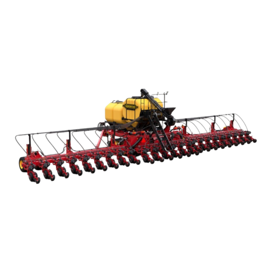
Introduction Description of the Machine Tempo K Planter Bar Congratulations on the choice of a Tempo K Planter Bar Tempo K is available in 30" spacing. The planter bar to complement the farming operation. These units have features a positive air pressure system that holds the seed been engineered for high capacity, high speed planting;... -
Page 6: Illustrations Of The Machine
Introduction Illustrations of the Machine Figure 1.1 Tempo K 24R30 (Front) Figure 1.2 Tempo K 24R30 (Rear) 904164-en-us; 18.09.2024... -
Page 7: Machine Serial Number
Record the machine model and serial number in the spaces provided below. Use these numbers when contacting the dealer for repair parts, warranty or service assistance. Serial Number(s) Implement(s) Serial Range: 000000 - 000000 Implement Model Serial Number(s) Tempo K Other 904164-en-us; 18.09.2024... -
Page 8: Technical Data Sheet
Introduction Technical Data Sheet Table 1.1 Technical Data Sheet: 2025 Tempo K Planter Bar Models TPK 60’ 24 Row 30” Frame Specifications Primary Toolbar Size 10 x 10 in (25.4 x 25.4 cm) Secondary Toolbar Size 7 x 7 in (17.78 x 17.78 cm) Flexibility ±12°... -
Page 9: Notes
Introduction Notes 904164-en-us; 18.09.2024... -
Page 10: Safety
Safety Safety Safety Alert Symbols IMPORTANT! The information next to this symbol may be worth noting since it is a hint 2.1.1 Safety Information containing particularly useful information on how to handle the machine. Failure to follow The Safety Alert Symbol(s) are intended to direct the these notices may result in damage to the attention of the machine user to important safety machine. -
Page 11: Hand Signals
Safety Hand Signals Hand signals are an important means of communication on farms where noise levels and distance can hinder regular communication between workers. These 11 hand signals were created so that two or more persons can communicate effectively and safely. Table 2.1 Hand Signals Lower Equipment: Make a circular Raise Equipment: Make a circular... -
Page 12: Operator Responsibilities
Safety Operator Responsibilities DO NOT allow riders on any part of the implement. Responsibility for the safe operation, adjustment, maintenance and repair of this machine falls to the main user. It is the responsibility of the owner, or authorized person in charge, to ensure all persons who operate, When parking, park the machine and the tractor on a solid adjust, maintain and/or repair this implement be familiar level surface. -
Page 13: Maintenance Safety
Safety Maintenance Safety Hydraulic Safety Read and understand all information provided in the Always place all tractor hydraulic controls in neutral Operator’s Manual covering operation, adjustment, before dismounting. maintenance and repair prior to performing any of these Ensure that all hydraulic system components are kept tasks. -
Page 14: Electrical Safety
Safety Electrical Safety Be aware that the implement is wider than the tractor when transporting. Always have the wings completely folded (if equipped) when transporting on public roads. Ensure that the machinery is shut off and all electrical components are disconnected before doing any work on Watch for overhead wires and other obstructions. -
Page 15: Hazards
Safety 2.12 Hazards Be careful when operating along the side of a road or building. Rocks or other debris can be The key is to recognize hazards while working or living thrown from the machine during operation on a farm; avoid dangerous situations or at least minimize possibly resulting in injury. -
Page 16: Anhydrous Ammonia (Nh3) Safety
Safety 2.13 Anhydrous Ammonia (NH3) Safety • Before each day’s use: • Visually inspect all system plumbing components for functionality, excessive wear, and damage. Anhydrous ammonia (NH3) under pressure can • Some components may have recommended cause severe burning, blindness, sickness, or "replace by"... - Page 17 Safety In the event of an exposure emergency, the most In the event of a control system failure, the flow important resource is an ample supply of clean water to control valve may remain open. To ensure there begin flushing the eyes and skin. If using a vehicle to is a means by which flow can be shut off at the transport anhydrous ammonia, there must be a 19 L (5 source, a master on / off control shall be present...
- Page 18 Safety Safety Signage: If operating on a highway, outfit the tank Remain upwind when depressurizing the system. with all required safety markings, including a slow- And the nurse tank valve shall only be open moving vehicle (SMV) sign. during operation. •...
-
Page 19: Safety Signs
Safety 2.14 Safety Signs 2.14.1 Location of Safety Signs (X) refers to the decal(s) at each location. Refer to Section “2.14.3 Decals on page 19“ for more information on each decal. Figure 2.1 TPK Frame Decal Locations 904164-en-us; 18.09.2024... - Page 20 Safety Figure 2.2 TPK Frame Decal Locations (Rear) 904164-en-us; 18.09.2024...
-
Page 21: Marker Lamps
Safety 2.14.2 Marker Lamps The machine is equipped with two red lamps (1) located toward the rear center of the machine. The machine has marker lamps that must be used when The machine is equipped with two amber lamps (2) moving the machine in the folded position on roads. - Page 22 Safety Marker Lamps II Legend • (F) 3/8 x 7 x 8–1/4 U-Bolt • (G) SMV Emblem • (A) Amber Light LED • (H) SMV Bracket • (B) Red Light • (I) BLT Hex 3/16–24NC x 3/4 5Z • (C) Light Bracket •...
-
Page 23: Decals
Safety 2.14.3 Decals Decal Image Decal Name Description Tongue Latch Lock Heed all instructions. Valve Part may lower without warning. Turn WARNING off the engine, remove the key, relieve the pressure before maintenance or repair. Foot Crushing Refer to the operator manual for correct Hazard service procedures. - Page 24 Safety Decal Image Decal Name Description The maximum speed safety sign displays SIS Decal — 15 mph the maximum speed to transport the machine. Avoid potential pinch points. Take extra WARNING caution when working around moving Crushing Hazard parts. WARNING Stay clear of area around row marker when engine is running.
-
Page 25: Notes
Safety 2.15 Notes 904164-en-us; 18.09.2024... -
Page 26: Operation
Operation Operation Quick Start Guide The quick start guide is designed for quickly getting to work on the field. Each section contains references to the section in the manual that describes the process in detail. If you have the slightest doubt, read the detailed description. Hitching •... -
Page 27: Tractor Requirements
Operation Tractor Requirements 1. Recommended temperature range for hydraulic oil. 2. Outside the recommended temperature range for the hydraulic oil. The tractor cab must be designed so that it 3. Hydraulic oil temperature without guaranteed protects the operator from debris and dust which function and with reduced life expectancy. -
Page 28: Control System
Operation Control System • (9) Wing Wheel Leg • (10) Wing Wheel Mount All machine functions are controlled and monitored from • (11) Belt Conveyor the tractor cab using a control unit. Väderstad offers • (12) Rear Staircase options for controlling and monitoring the machine using an iPad. -
Page 29: Hitching & Unhitching
Operation Hitching & Unhitching 3.4.1 Hitching Make sure there are no persons or obstructions between the tractor and the machine. Figure 3.5 Tractor Connection III 7. Retract the hitch jack. Move the hitch jack to the storage position (7) and fasten with pin. The location and position of the storage location of the hitch jack can vary. -
Page 30: Unhitching
Operation 3.4.2 Unhitching 5. Remove the pin from the tractor draw-bar and disconnect the safety transport chain between the machine and the tractor. Disconnect the tractor from the planter in the 6. Move the tractor draw-bar so the draw-bar does not transport position only. -
Page 31: Hydraulic Connections
Operation Hydraulic Connections Always begin by connecting the free return and, where appropriate, the case drain. The hydraulic hoses on the machine have color-coded, quick-release couplings and there are illustrative decals on the frame to help avoid incorrect connection. Make sure that the hoses are connected in colored pairs to the correct hydraulic couplings The tractor must always be switched off during on the tractor. -
Page 32: Hose Length Adjustment
Operation Hose Length Adjustment 3.7.1 Work Lights Adjust the hose length using the hose holder. Work lights must be used when driving on the road. When the hydraulic hoses are disconnected from the tractor, they should be secured in the hose holder. The work lights are controlled through E-control. -
Page 33: Track Operation
Operation Track Operation The track system can operate in very bad conditions; for operator and machine safety, be sure to know your surroundings. 3.9.1 New Track Break-In The track system is free to pivot around the main axle Operate the new tracks in dry and dusty soil conditions as following the ground conformation. -
Page 34: Folding The Machine
Operation 3.10 Folding the Machine 8. Once the wings have completely forward folded and the wing hook frames contact the brace arms, lower the lift circuit (yellow) until the wing axles are Procedure completely retracted. 1. Start the tractor engine, release the brakes and shift to 9. -
Page 35: Transport Locks
Operation 3.10.1 Transport Locks When not in use, store the transport locks and depth stop collars in the storage position (3). Install transport locks The machine is equipped with transport locks and depth when machine is completely unfolded before doing any stop collars. -
Page 36: Unfolding The Machine
Operation 3.11 Unfolding the Machine When in working position, ensure wing fold cylinders are fully extended prior to field operation. Before starting the procedure: • Make sure there is 6.7 m (25 ft) clearance behind the planter for unfolding. • The tractor must roll slightly as the frame is unfolded. -
Page 37: Road The Machine
Operation 3.12 Road the Machine Machine electrical shock and electrocution hazard. Personal injury or death can occur. Keep 3.12.1 Preparation the machine clear of overhead electrical power lines. Procedure 1. Make sure the large frame planter toolbar is connected according to the procedures outlined. Procedure 2. -
Page 38: Central Seed Fill System
Operation 3.13 Central Seed Fill System Initial Start Up: For all crops, the plenum gate should be set to the Central Fill System Legend maximum open setting. • (A) Plenum Adjust the tractor hydraulic remote flow to achieve the • (B) Fan correct CFS pressure for the seeds being planted. -
Page 39: Central Seed Fill Air Pressure
Operation 3.13.3 Central Seed Fill Air Pressure 3.13.4 Fill the Seed Tanks with the Belt Conveyor (if equipped) A hydraulically driven blower (1) at the rear of the central fill hoppers maintains air pressure for delivering seed to We always recommend mixing talc in the seed to the row units. -
Page 40: Remove The Seed From The Central Seed Fill System
Operation 3.13.5 Remove the Seed from the Central Seed Fill 10. Start the Central Seed Fill fan to blow the seed out of System each plenum (3) and all the horizontal seed tubes into a vented container. Procedure 11. Stop the Central Seed Fill fan. 1. -
Page 41: Lamp Operation
Operation 3.14 Lamp Operation For lamp operation, the tractor hazard flashers must be ON or the machine lamps will not The machine lighting system includes a turn signal operate. module that causes the machine lamps to operate differently than some tractor / machine lighting systems. 3.14.1 Day Operation Table 3.5 Lamp Operation... -
Page 42: Field Operation
Operation 3.15 Field Operation Procedure 1. Unfold the machine. (Refer to Section “3.11 3.15.1 Operate in the Field Unfolding the Machine on page 32“) 2. Confirm that the ball valve is in the closed position Personal injury or machine damage can occur. (1) for planting. -
Page 43: Center Section (Leveling)
Operation 3.16 Center Section (Leveling) Figure 3.23 Leveling I The center section (1) is set to run one inch higher than the bolts higher or lower as desired. Make sure to add this the wings (2). The center section carries more weight than hardware to both sides to prevent any twisting on the lift the wings. -
Page 44: Planting Recommendations
Operation 3.17 Planting Recommendations • (C) Number of agitators, which gives 32 in the example. 3.17.1 Output Settings for Sowing / Planting Ex. 3255P-32 3.17.1.1 Output Settings Matrix Explanation of Seed Disk Type No. • (A) Number of holes, which gives 32 in the example. •... -
Page 45: Table 3.7 Seed/Ha I
Operation 3.17.1.2 Theoretical Maximum Speed (km/h) Note that the speed indication is only a theoretical maximum speed. Always adjust your speed to suit the prevailing field conditions! Table 3.7 Seed/ha I 18, 9 50 000 18, 0 16, 8 15, 8 60 000 15, 4 14, 4... -
Page 46: Table 3.8 Seed/Ha Ii
Operation Table 3.8 Seed/ha II 19, 7 18, 5 100 000 19, 2 17, 9 16, 8 110 000 17, 6 16, 4 15, 4 120 000 16, 9 15, 7 14, 8 125 000 19, 7 14, 1 13, 1 12, 3 19, 5 150 000... -
Page 47: Table 3.9 Seed/Ha Iii
Operation Table 3.9 Seed/ha III 175 000 18, 7 200 000 17, 7 16, 6 225 000 17, 1 15, 9 14, 9 250 000 19, 9 14, 2 13, 3 12, 5 19, 2 18, 0 300 000 19, 0 17, 1 12, 2 11, 4... -
Page 48: Notes
Operation 3.18 Notes 904164-en-us; 18.09.2024... -
Page 49: Troubleshooting
Troubleshooting Troubleshooting Inductive Sensor Electrical, hydraulic and mechanical components are used to control the machine. Work methodically and, step by step, eliminate possible sources of error using the troubleshooting page. Hydraulic Electric Valves Figure 4.2 Inductive Sensor • Reacts to metal objects passing within a distance of 1 —... -
Page 50: Seed Counter / Sensor
Troubleshooting Seed Counter / Sensor List of Conditions for Seed Output The machine is in working mode • If the machine has been raised above the ‘output start’ level, metering will not begin until the machine height comes under the ‘output start’ level. •... -
Page 51: Troubleshooting The Tempo K
Troubleshooting Troubleshooting the Tempo K Table 4.2 Troubleshooting the TPK I Possible Solution(s) Issue The home screen does not show any air Check that the speed sensor to the fan is functioning. pressure although the fan is running. Increase weight transfer on the row unit. -
Page 52: Table 4.3 Troubleshooting The Tpk Ii
Troubleshooting Table 4.3 Troubleshooting the TPK II Possible Solution(s) Issue Check that the air pressure is 3.5 kPa (0.035 bar). Check that the singulator is not damaged. The singulator must be set to a very low value. Check that the correct seed disc is installed. Try using a seed disc with a smaller hole. -
Page 53: Notes
Troubleshooting Notes 904164-en-us; 18.09.2024... -
Page 54: Maintenance
Maintenance Maintenance Maintenance Schedules The following will list standard checks, frequency and other information regarding repairs. Table 5.1 Maintenance: Tempo K Planter Bar Component Freq. (Hrs) Procedure Weekly Lubricate with pressure gun, using multi-purpose grease. Lubricate the Hitch (40) Lubricate the Wing Brace Weekly Lubricate with pressure gun, using multi-purpose grease. -
Page 55: Tools
Maintenance Tools 5.3.2 End of the Day Clean collected chemicals off of the planter. To make maintenance and service work easier, the machine’s mounting elements are standardized. No special tools are required for daily maintenance. Use same precautions as in the chemical manufacturer’s instructions when you clean up Recommended Tools chemicals as when you fill the toolbar. -
Page 56: When Storing For Longer Periods
Maintenance 5.3.4 When Storing for Longer Periods • Store the toolbar away from livestock. • When the machine is not being used, it should be stored indoors. This is very important given that the Use same precautions as in the chemical machine has electronic instruments. -
Page 57: Adjustment For Field Position
Maintenance Adjustment for Field Position Figure 5.2 Field Position Adjustment I Field Position Adjustment Legend • Tighten the bolts. • Repeat these steps for the other wing. • (A) Inner Wing • (B) 1 x 3–1/2 Bolt • (C) 2 x 8–3/4 Pin •... -
Page 58: Hydraulic Belt Drive
Maintenance Hydraulic Belt Drive 5.5.3 Adjusting the Tension of the Belt 5.5.1 Maintenance & Service of the Hydraulic Motor • After operating for 500 — 700 hectares, we recommend a careful check of the fan and the fan belt. • Make sure the belt is properly tensioned in accordance with the recommendations. -
Page 59: Fan Noise
Maintenance 5.5.4 Fan Noise Noise Level: 83.6 dB (A). Sounds Output: 104.4 dB (A). Microphone positioning according to standard EN ISO 4254–1, measuring uncertainty ±2 dB (A). 5.5.5 Replacing the Belt 1. Release the belt tension in accordance with Section “5.5.3 Adjusting the Tension of the Belt“. -
Page 60: Track System
Maintenance Track System 2. Loosen the cap screw (3) counterclockwise 1.0 to 1.5 turns on the side of the undercarriage that is necessary for the track to move towards. 5.6.1 Track Tension 3. Tighten the cap screw on the opposite side to (221 lb/ The tension is set at the factory and no adjustment during ft) (300 N.m). -
Page 61: Bleeding Air From The Hydraulic Lift System
Maintenance Bleeding Air from the Hydraulic Lift Do not loosen any hydraulic fittings to bleed air System from the system. Before starting the procedure. 5. Raise the machine. Continue to hold the tractor lever to let oil bypass and fill each wing lift cylinder. Leaking fluid under pressure can enter the skin 6. -
Page 62: Bleeding Air From The Hydraulic Fold System
Maintenance Bleeding Air from the Hydraulic 2. Stop the engine, apply the park brake and take the key with you. Fold System 3. Connect the fold system hoses to the tractor. 4. Make sure the tractor reservoir is full of the hydraulic Leaking fluid under pressure can enter the skin oil required by the manufacturer. -
Page 63: Cleaning Procedures
Maintenance Cleaning Procedures 5.9.1 CFS Clean-Out Procedure 1. When tank runs empty; Open seed gate all the way. 2. Turn off CFS Fan. 3. Open lid on tank being cleaned out and brush away any left over product down into plenum. Close tank lid and latch. -
Page 64: Lubrication Points
Maintenance 5.10 Lubrication Points See the machine specifications for the correct lubricant. Shut off the engine, lower the machine to the ground, set the parking brake and the key with you. Make sure to clean the lubrication fittings fully before connecting the grease gun. - Page 65 Maintenance Lubrication point Lubrication point Pos. Interval Pos. Interval Primary lift cylin- Wing pivot points Each week Each week ders (2x) (2x) Lubrication point Lubrication point Pos. Interval Pos. Interval Hitch-swivel Each week Main hinge (2x) Each week Lubrication point Pos.
-
Page 66: Wheel Bearing Assemblies
Maintenance 5.11 Wheel Bearing Assemblies The spindle nuts on the wheel assemblies are set at the factory. Road transport and field work will seat the bearings. More adjustment on the bearings will be necessary. After Lubrication point Pos. Interval 20 hours of machine operation remove the grease cap and Tilt Bearing (6x) check if the bearings are tight. -
Page 67: Prime The Hydraulic Circuits
Maintenance 5.12 Prime the Hydraulic Circuits 4. With all connections attached and if the cylinders have support it will let the rod extension apply pressure to the system. The main or base cylinder Before you release air from (priming) the must extend as oil flows into the bottom of the hydraulic circuits, select an area with a hard, cylinder. -
Page 68: Notes
Maintenance 5.13 Notes 904164-en-us; 18.09.2024... -
Page 69: Specifications
Specifications Specifications Implement Specifications Table 6.1 Specifications: 2025 Tempo K Planter Bar Models TPK 60’ 24 Row 30” Frame Specifications Primary Toolbar Size 10 x 10 in (25.4 x 25.4 cm) Secondary Toolbar Size 7 x 7 in (17.78 x 17.78 cm) Flexibility ±12°... -
Page 70: Standard Bolt Torques
Specifications Standard Bolt Torques When replacing a bolt, use only a bolt of the same grade or higher. Except in shear bolt applications, where you must use the same grade bolt. Failure to follow these instructions may result in personal injury and/or equipment damage. Bolt Grades •... -
Page 71: Hydraulic Connection Torques
Specifications Hydraulic Connection Torques Table 6.3 Straight Thread O-ring Boss (ORB) Hydraulic Connection Torques Legend Jam Nut or Straight Fitting Torque Dash Size • (1) Straight Thread O-ring Boss (ORB) ft/lbs Newton Meters • Example: 12MB — 12MJ is —12 male ORB to 13 —... -
Page 72: Electrical System
Specifications Electrical System Table 6.5 Pinout Legend: ISO 11783 6.4.1 ISO 11783 Power Supply, Gateway Function Electrical Ground Electrical Control Unit, Ground Voltage (12 V) Electrical Control Unit (12 V) CAN High CAN Low Figure 6.3 ISO 11783 Pinout 904164-en-us; 18.09.2024... -
Page 73: Tpk Electrical Layout
Specifications 6.4.2 TPK Electrical Layout Overview • (A) Front & Middle Section (Worklights) • (B) Rear Section • (C) Left Wing • (D) Middle Wing Section • (E) Right Wing • (F) Row Units • (G) Marking Tables 904164-en-us; 18.09.2024... -
Page 74: Hydraulics
Specifications Hydraulics 6.5.1 Wing Folding Figure 6.4 Wing Folding Hydraulics 904164-en-us; 18.09.2024... -
Page 75: Central Seed Fill Fan, Support Wheels
Specifications 6.5.2 Central Seed Fill Fan, Support Wheels Central Seed Fill Fan, Support Wheels Legend • 1.A connects to 2.A • 1.B connects to 2.B Figure 6.5 Central Seed Fill Fan, Support Wheels 904164-en-us; 18.09.2024... -
Page 76: Support Stand
Specifications 6.5.3 Support Stand Figure 6.6 Hydraulic Support Stand 904164-en-us; 18.09.2024... -
Page 77: Wings Weight Transfer
Specifications 6.5.4 Wings Weight Transfer Wings Weight Transfer Legend • 2.A connects to 1.A • 2.B connects to 1.B • 2.C connects to 3.C or 4.C • 2.D connects to 3.D or 4.D 904164-en-us; 18.09.2024... - Page 78 Specifications Figure 6.7 Wings Weight Transfer 904164-en-us; 18.09.2024...
-
Page 79: Row Unit Weight Transfer
Specifications 6.5.5 Row Unit Weight Transfer Row Units Weight Transfer Hydraulics Legend • 3.C connects to 2.C • 3.D connects to 2.D 904164-en-us; 18.09.2024... - Page 80 Specifications Figure 6.8 Row Units Weight Transfer Hydraulics 904164-en-us; 18.09.2024...
-
Page 81: Individual Hydraulic Row Unit Weight Transfer (Option)
Specifications 6.5.6 Individual Hydraulic Row Unit Weight Transfer (Option) Individual Hydraulic Row Unit Weight Transfer Legend • 4.C connects to 2.C • 4.D connects to 2.D 904164-en-us; 18.09.2024... - Page 82 Specifications Figure 6.9 Individual Hydraulic Row Unit Weight Transfer 904164-en-us; 18.09.2024...
-
Page 83: Hydraulic Diagram Functions
Specifications Hydraulic Diagram Functions Table 6.6 Hydraulic Diagram Function Descriptions I Type Parent Label Function Row unit pressure Accumulator Row unit pressure Accumulator Row unit pressure Accumulator Frame pressure Accumulator Manifold Pilot check valve Wing fold and frame tilt Manifold Central seed fill fan speed control Manifold Wings weight transfer... -
Page 84: Table 6.7 Hydraulic Diagram Function Descriptions Ii
Specifications Table 6.7 Hydraulic Diagram Function Descriptions II Type Parent Label Function 3–way pressure re- Electrically controlled, removes weight from B33 — B57 ducing valve row units 2/2 valve normally Prevents row units to sink during headland open turns 2/2 valve normally Prevents row units to sink during headland E72–1 open... -
Page 85: Table 6.8 Hydraulic Diagram Function Descriptions Iii
Specifications Table 6.8 Hydraulic Diagram Function Descriptions III Type Parent Label Function Fixed manual setting with drain, transfer Pressure reducing weight to row unit valve M6 orifice cavity Empty, to restrict flow to row unit pressure M6 orifice cavity Empty, to restrict flow to row unit pressure Orifice adapter Restricts motor housing flush flow Orifice adapter... -
Page 86: Notes
Specifications Notes 904164-en-us; 18.09.2024... -
Page 87: Aftermarket
Aftermarket Aftermarket Warranty • Rubber Tire Warranty: Rubber tires are warranted directly by the respective manufacturer only and not by Väderstad Inc. Väderstad Inc. Limited Warranty Terms and Conditions — United States and Canada, 7.1.4 Owners Obligation Effective for Equipment Retailed and Delivered after May 21, 2021. -
Page 88: Additional Warranty Information
Aftermarket Väderstad Inc. as referred to herein with respect to Maintenance Service sales in: The owner’s manual furnished to you with the equipment at the time of delivery contains important maintenance United States & Canada: and service information. You must read the manual carefully and follow all the maintenance and service •... -
Page 89: Notes
Aftermarket Notes 904164-en-us; 18.09.2024... - Page 90 904164-en-us; 18.09.2024...
-
Page 91: Appendix
Appendix TABLES Table 1.1 Technical Data Sheet: 2025 Tempo K Planter Table 4.3 Troubleshooting the TPK II ....... 48 Bar ..............4 Table 5.1 Maintenance: Tempo K Planter Bar..... 50 Table 2.1 Hand Signals ..........7 Table 6.1 Specifications: 2025 Tempo K Planter Table 3.1 Hydraulic Oil Temperature Req. - Page 92 Appendix FIGURE Figure 1.1 Tempo K 24R30 (Front) ......2 Figure 3.25 Seed Disk Type No. Example....40 Figure 1.2 Tempo K 24R30 (Rear) ......2 Figure 4.1 Hydraulic Electric Valves ......45 Figure 1.3 Serial No. Decal........3 Figure 4.2 Inductive Sensor ........45 Figure 2.1 TPK Frame Decal Locations.....
-
Page 93: Index
Index Index Maintenance Safety..........9 Safety Sign Information ...........6 Anhydrous Ammonia (NH3) Safety ......12 Standard Bolt Torques ........... 66 Storage Safety............10 Electrical Safety ........... 10 Technical Data Sheet ..........4 Hand Signals ............7 Tire Safety ............10 Hazards .............. 11 Transport &... - Page 94 PO Box 1030 Wahpeton, ND 58075, USA Where farming starts...
Need help?
Do you have a question about the Tempo K and is the answer not in the manual?
Questions and answers