Advertisement
Quick Links
Advertisement

Related Manuals for Walker Edison Elias ELIB5B


Summary of Contents for Walker Edison Elias ELIB5B
- Page 1 Item: ELIB5B Revised 03/2024-V1...
- Page 2 hammer and tape measure is required for the assembly of this product.
- Page 3 The side drawer with WARNING LABEL, should be mounted in highest drawer. 01 pc 04 pcs 01 pc Small right drawer front 01 pc 02 pcs 01 pc Small drawer back 06 pcs 01 pc Bottom panel 04 pcs Front Rail 01 pc Drawer front Top back panel...
- Page 4 Ø8*30mm Wooden dowel Screw 24 pcs Ø3,5*30mm 42 pcs Ø6,0*8mm Screw 18 pcs Screw Ø6,0*20mm Ø15*12mm Cam lock Ø3,5*14mm Screw Screw Ø7*80mm Screw Ø4,0*20mm Cam bolt Ø6*31mm Ø4,0*40mm Screw Ø6*35mm Plastic bush Threaded foot insert Leveling foot Wall anchor Washer Phillips...
- Page 5 Felt Sticker Ø30mm Plastic fixing Ø26mm device Right Drawer Ø250mm slide support Left Drawer Ø250mm slide support Right Drawer Ø250mm slide Left Drawer Ø250mm slide Handle Hex Key 50x50x50mm...
- Page 6 Step 1 Insert wood dowel (A) into parts 02, 03, 05, 08, 11, 12, 18, 19, 21 and 26. Ø8*30mm...
- Page 7 Step 2 1 - Ensure cam bolt is installed straight and not at an angle. 2 - Tighten cam bolt until shoulder on cam bolt is flush. Do not over-tigh- ten. Attach cam bolt (I) into the holes in parts 01, 02, 03, 13,16 and 20 with Phillips head screwdriver.
- Page 8 Step 3 Tap the Plastic fixing device (Q) carefully. Use a hammer to tap the Plastic fixing device (Q) into parts 02 and 03.
- Page 9 Step 4 Secure Right side slide support to part 10 and 03 with screw (D) and phillips head screwdriver. Pay attention to the identification Ø6,0*20mm Ø3,5*14mm Secure Right side slide support to part 10 with screw (F) and phillips head screwdriver. ø250mm...
- Page 10 Step 5 Secure Left side slide support to part 10 and 02 with screw (D) and phillips head screwdriver. Pay attention to the identification Ø6,0*20mm Secure Left side slide support Ø3,5*14mm to part 10 with screw (F) and phillips head screwdriver. ø250mm P.10...
- Page 11 Step 6 Secure Right side slide support to part 08 with screw (C) and phillips head screwdriver. Pay attention to the identification Secure Right side slide support to part 08 with screw (F) and phillips head screwdriver. Ø6,0*8mm Rotate 180° Ø3,5*14mm ø250mm P.11...
- Page 12 Step 7 Secure Left side slide support to part 08 with screw (C) and phillips head screwdriver. Pay attention to the identification Ø6,0*8mm Secure Left side slide support Ø3,5*14mm to part 08 with screw (F) and phillips head screwdriver. ø250mm P.12...
- Page 13 Use a hammer to tap the Threaded foot insert (L) Step 8 into the hole of part 09. Insert Leveling foot (M) into the Threaded foot insert (L) and rotate until the part fits fully. Tap the Threaded foot insert (L) carefully. Secure part 09 to part 04 with screw (G) and tighten with a Hex Key (W).
- Page 14 Step 10 Remove the felt sticker (P) from the paper. Glue the felt to the bottom of the foot. ø30mm Step 11 50x50x50mm Attach parts 26 to part 04, using screws (G) and tighten with hex key (W). Ø7*80mm P.14...
- Page 15 Step 12 Attach part 02 to part 04 with Screw (J) and Phillips head screwdriver. Ø4,0*40mm Step 13 Attach part 08 to part 04 with Screw (J) and Phillips head screwdriver. Ø4,0*40mm P.15...
- Page 16 Step 14 Align the opening in cam lock to the cam bolt and press into opening. Using a screwdriver, rotate the cam lock until it engages with the cam bolt and locks in place (anywhere between 90-180 degrees). Do not over-tighten the cam lock.
- Page 17 Step 15 Rotate 90° Fit part 03 to parts 04 and 05. Attach part 03 to part 04 with Screw (J) and Phillips head screwdriver. Ø4,0*40mm Insert Cam lock (E) in the hole of the part 05 and attach with a Phillips head screwdriver. Ø15*12mm P.17...
- Page 18 Step 16 Insert parts 06 and 07 between the grooves of parts 02 and 03. Two people are needed to this step. Name and address of the supplier and date of production. BACK Fit parts 01 to parts 02, 03 and 08. P.18...
- Page 19 Step 17 Secure part 07 to parts 02 and 03 with screw (J) and Phillips head screwdriver. Ø4,0*40mm Step 18 FRONT Insert Cam lock (E) in the hole of the part 08 and attach ø4,0*20mm with a Phillips head screwdriver. Attach parts 02 and 03 to part 01 with screw (H) and Phillips head screwdriver.
- Page 20 Step 19 Attach part 11 and 12 to part 16.Insert Cam lock (E) into the holes in the parts 11 and 12, and attach with Phillips head screwdriver. Ø15*12mm Step 20 Insert part 15 between the grooves of parts 11 and 12. Secure part 17 to parts 11 and 12 with screw (B) and Phillips head screwdriver.
- Page 21 Step 21 Attach part 18 and 21 to part 20. Insert Cam lock (E) into the holes in the parts 18 and 21, and attach with Phillips head screwdriver. Attach part 18 and 19 to part 13. Insert Cam lock (E) into the holes in the parts 18 and 19, and attach with Phillips head screwdriver.
- Page 22 Step 23 Ø3,5x14 Attach handle (V) into part 16 with screw (F) and Phillips head screwdriver. Step 24 Ø3,5x14 Attach handle (V) into parts 13 and 20 with screw (F) and Phillips head screwdriver. P.22...
-
Page 23: Right Side
Step 25 Secure Right drawer slide (T) into parts 12,19 and 21 with screw (C), tighten with a Phillips head screwdriver. Secure Left drawer slide (U) into parts 11 and 18 with screw (C), Rotate 90° tighten with a Phillips head screwdriver. Right side Left side ø250mm... - Page 24 Step 26 1 - Fit the Right drawer slide into the Right side slide support (R). 2 - Fit the Right drawer slide (U) into the Right side slide support (S). Fit the assembled drawers between parts 02, 08 and 03. Step 27 Rotate the Leveling foot to align it with the floor.
- Page 25 Step 28 Wall anchor and hardware are included with this product. Please make sure hardware is suitable for your walls before types of anchors. Ø6mm Attach part (N) with screw (H) and washer (O), in the frame of top panel unit using Phillips head screwdriver. With drilling machine make one hole in the wall, insert part (K) in the hole.
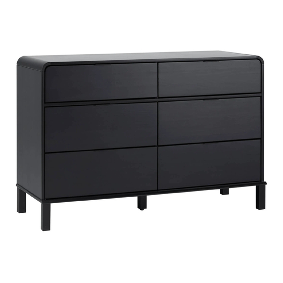
- Page 26 Step 29 Assembly Complete! 124 lbs 56 kg 15 lbs 6 kg 20 lbs 9 kg P.26...
Need help?
Do you have a question about the Elias ELIB5B and is the answer not in the manual?
Questions and answers