
Subscribe to Our Youtube Channel
Related Manuals for THORLABS vytran PTR404B


Summary of Contents for THORLABS vytran PTR404B
- Page 1 PTR404B Recoater with Manual Recoat Assembly (100 mm Length) User Manual Mold Assembly and Fiber Holding Block Inserts Sold Separately...
-
Page 2: Table Of Contents
Fiber Recoater with Manual 100 mm Recoat Assembly Table of Contents Warning Symbol Definitions ..................... 1 Chapter 1 Safety........................... 2 Chapter 2 Description ......................... 3 Chapter 3 3.1. Introduction ........................3 3.2. Parts Checklist ......................3 Device Selection ........................ 5 Chapter 4 4.1. - Page 3 9.3.6. Replace and Align Mold Assembly ..................36 9.3.7. Replace Inserts ........................37 Chapter 10 Specifications ........................38 Chapter 11 Material Data Safety Sheet ....................39 Chapter 12 Compliance ........................47 Regulatory ........................48 Chapter 13 Thorlabs Worldwide Contacts ..................49 Chapter 14...
-
Page 4: Chapter 1 Warning Symbol Definitions
Fiber Recoater with Manual 100 mm Recoat Assembly Chapter 1: Warning Symbol Definitions Warning Symbol Definitions Chapter 1 Below is a list of warning symbols you may encounter in this manual or on your device. Symbol Description Direct Current Alternating Current Both Direct and Alternating Current Earth Ground Terminal Protective Conductor Terminal... -
Page 5: Chapter 2 Safety
Fiber Recoater with Manual 100 mm Recoat Assembly Chapter 2: Safety Safety Chapter 2 WARNING Appropriate eye protection should always be used when staring at a mold to prevent unwanted exposure to UV light, especially when the mold lid is open. WARNING UV curable acrylate recoat materials can be hazardous to your health if not handled properly. -
Page 6: Chapter 3 Description
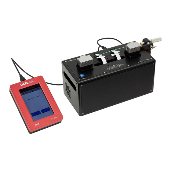
Top Inserts for Fiber Holding Blocks (Purchased Separately) • UV-Curable Acrylate Recoat Material (Purchased Separately) • Manual Injector • If Ordered Separately: Injection Syringes and Cap If you are missing any of the above or need replacements, please contact Thorlabs. Rev A, January 10, 2021 Page 3... - Page 7 Fiber Recoater with Manual 100 mm Recoat Assembly Chapter 3: Description Figure 1 System Components Page 4 TTN176295-D02...
-
Page 8: Chapter 4 Device Selection
Ø280 µm, Ø430 µm, or Ø600 µm fiber coatings. Custom mold sizes up to Ø900 µm are available; please contact Thorlabs for more information. Additional mold assemblies may also be purchased and swapped out by the user. The assembly simply screws to the top of the device, making the removal and installation simple and easy. -
Page 9: Chapter 5 Setup
Fiber Recoater with Manual 100 mm Recoat Assembly Chapter 5: Setup Setup Chapter 5 5.1. Attaching the Manual Recoat Injector You will need to attach the manual recoat injector to the side of the unit. Place the injector on the side of the unit and attach it to the unit using the two cap screws from the attached bag. -
Page 10: Attaching The Recoat Mold Assembly
Fiber Recoater with Manual 100 mm Recoat Assembly Chapter 5: Setup 5.3. Attaching the Recoat Mold Assembly Make sure that the base plate and bottom of the mold assembly are cleaned of any dirt particles. Plug the male ribbon cable connectors that hang from the bottom of the recoat mold into the female ribbon cable connectors that stick out of the center slot on the unit. -
Page 11: Connecting The Wires
Fiber Recoater with Manual 100 mm Recoat Assembly Chapter 5: Setup 5.4. Connecting the Wires Plug in the AC power cord. The power supply accepts an AC input of 100 - 240 VAC; 47 - 63 Hz. Connect the AC power cord to the external power supply. -
Page 12: Priming The Mold
Fiber Recoater with Manual 100 mm Recoat Assembly Chapter 5: Setup Plug this USB plug into the top USB socket of the handset. Note that the USB socket on the side of the handset is dedicated to connecting a USB flash drive for importing/exporting fiber files and updating software. -
Page 13: Chapter 6 Control
Fiber Recoater with Manual 100 mm Recoat Assembly Chapter 6: Control Control Chapter 6 The PTR404B can be operated using the blue “Cure” button on the unit, or via the Handset Controller. 6.1. Handset Controller The handset Controller is used for changing curing parameters and can also be used to start the curing process. - Page 14 Fiber Recoater with Manual 100 mm Recoat Assembly Chapter 6: Control Figure 8 PTR404B Main Screen This main screen will show the current file name (only if the parameters of the unit match the parameters of a saved fiber file), and the cure time, just below the menu. To start Curing, press ‘Cure’.
- Page 15 Fiber Recoater with Manual 100 mm Recoat Assembly Chapter 6: Control Figure 9 Main screen showing cure macro and load fiber macro statuses Pressing the edit button in the toolbar will show relevant parameters (along with the current value) on the screen. Swipe the list to scroll up / down, touch a parameter to select it for editing.
-
Page 16: Ptr404B Parameters
Fiber Recoater with Manual 100 mm Recoat Assembly Chapter 6: Control 6.5. PTR404B Parameters The following sections describe the parameters that control the PTR404B. 6.5.1. Cure Parameters The LEDs are numbered in sets of four from 1 to 7 starting from the outside. The Cure parameters are defined as follows: Cure Time: The duration of the recoat material cure (1 to 480 seconds) -
Page 17: Handset Controller Reference
Vytran LDC / PTR unit, the handset controller will turn on and will require approximately 1 minute of bootup time. At this time, the screen will display the Thorlabs logo which may flash a few times. - Page 18 Fiber Recoater with Manual 100 mm Recoat Assembly Chapter 6: Control Open File: Open a fiber file that has been saved onto the internal storage of the Handset Controller. Figure 13 Open File will list current files saved to the handset Save File: Overwrite the current fiber file with any changes that have been made to the parameters.
-
Page 19: Tools Menu Screen
Fiber Recoater with Manual 100 mm Recoat Assembly Chapter 6: Control Delete File: Delete any fiber file that has been saved to the internal storage of the Handset Controller. Export Files: Export any saved fiber file on the Handset Controller to a connected USB flash drive plugged into the side USB port. -
Page 20: Process Counters
Fiber Recoater with Manual 100 mm Recoat Assembly Chapter 6: Control 6.7.3. Process counters The process counter screen will show the total time the recoat lamp bulbs have been on during the cure cycle. The format reads hours:minutes:seconds. Toolbar – Process counter Screen Figure 16 The user can also reset the total cure time counter from this menu. -
Page 21: Terminal
Fiber Recoater with Manual 100 mm Recoat Assembly Chapter 6: Control 6.7.4. Terminal The handset controller provides a command terminal to send and receive commands to the PTR404B. To send a command, select the line just above the “Send” and “Close” buttons. This will open a keyboard for sending commands. -
Page 22: Version
Fiber Recoater with Manual 100 mm Recoat Assembly Chapter 6: Control 6.7.5. Version Selecting Version in the tools menu will open a screen that displays the unit’s Firmware version, macro file version, setup file version, and the handset controller version. Figure 18 Version menu The user will also have the ability to update the handset controller through this menu via USB. -
Page 23: User
Fiber Recoater with Manual 100 mm Recoat Assembly Chapter 6: Control 6.7.7. User With a password, users can protect the controller and its files from unauthorized access / modification. The controller defaults to No Password, Full Permission enabled. If a password has been setup and entered, the user can quickly log out using Log-Out. -
Page 24: Access Permissions
Fiber Recoater with Manual 100 mm Recoat Assembly Chapter 6: Control 6.7.8. Access Permissions The Handset Controller can be setup to prevent unauthorized access of files and parameters which can be read- only, no read or write, or full access. The Handset Controller defaults to No Password, Full Permission enabled. -
Page 25: Accidental Reboot
Fiber Recoater with Manual 100 mm Recoat Assembly Chapter 6: Control File Menu with “No read or write” enabled Figure 22 To disable this feature • Select Enter Password and type in the current password • Select Change Password and then select Ok to save a blank password •... -
Page 26: Chapter 7 Priming The Ptr404B
The recommended recoat material for use in this system is a high-index UV-curable acrylate material manufactured by Angstrom Bond (Item # AB950200, available on the Thorlabs website). Do not attempt to use alternate recoat materials without first consulting Thorlabs on compatibility with this device. -
Page 27: Priming The Injection System
Fiber Recoater with Manual 100 mm Recoat Assembly Chapter 7: Priming the PTR404B 7.2. Priming the Injection System The PTR404B comes standard with a remote manual recoat injector, which is fitted to the right side of the unit. This injection system provides a method of manually dispensing recoat material directly from the recoat bottle into the injection port. - Page 28 Fiber Recoater with Manual 100 mm Recoat Assembly Chapter 7: Priming the PTR404B 5. Turn the selection lever to the Fill position (lever down). Unscrew (turn counter-clockwise) the knurled syringe screw to draw recoat material from the bottle into the syringe. Continue unscrewing the syringe screw approximately 3/4"...
-
Page 29: Priming A Manual Injection Plunger (Not Standard)
7.3. Priming a Manual Injection Plunger (Not Standard) An alternative approach to injecting recoat material involves a “manual injection plunger.” This is does not come with the PTR404B and must be ordered separately. Contact Thorlabs technical sales if you are interested in this technique. -
Page 30: Chapter 8 Recoat Process
Fiber Recoater with Manual 100 mm Recoat Assembly Chapter 8: Recoat Process Recoat Process Chapter 8 The purpose of the recoat is to maintain the strength and flexibility of the fiber or fusion splice by protecting the glass surface from damage. It should be noted that recoating a splice does not make the splice stronger. To recoat fusion splice, the section of exposed fiber is placed in a quartz recoat mold assembly. -
Page 31: Recoating
Fiber Recoater with Manual 100 mm Recoat Assembly Chapter 8: Recoat Process 4. Double check that the exposed section of fiber is centered in the mold. Lower one of the holding block tops to clamp the fiber. 5. Make sure that the fiber is taut between the holding fixtures and lower the second holding top. The fiber should be held in line with the recoat mold channel. -
Page 32: Injection Using An Injection Plunger (Not Standard)
PTR404B. The injection plunger does not come with the PTR404B and must be ordered separately. Contact Thorlabs technical sales if you are interested in purchasing one. Once the fiber has been captured in the recoat mold assembly and the port has been loaded with recoat material, the injection plunger should be turned clockwise to inject the UV acrylate material into the mold cavity. -
Page 33: Curing The Coating
Fiber Recoater with Manual 100 mm Recoat Assembly Chapter 8: Recoat Process 8.2.3. Curing the Coating The liquid UV acrylate material cures to a solid state when exposed to ultra-violet light. The necessary UV radiation is provided by eight tungsten-halogen LEDs located below the bottom mold plate. The optical coating on the bottom plate ensures that any material which flows between the two plates will not cure and form a flashing on the recoated section of the fiber. -
Page 34: Chapter 9 Maintenance
Fiber Recoater with Manual 100 mm Recoat Assembly Chapter 9: Maintenance Maintenance Chapter 9 The purpose of the maintenance section is to define the planned maintenance requirements of the PTR404B. Where appropriate maintenance procedures are included. 9.1. Planned Maintenance The PTR404B fiber recoater is designed for a production environment to give trouble-free operation, provided normal planned maintenance is performed. -
Page 35: Empty The Manual Injection System
Fiber Recoater with Manual 100 mm Recoat Assembly Chapter 9: Maintenance To check the recoat LEDs, open the top of the recoat mold assembly and press the CURE button on the top of the device. This applies low power to the UV LEDs for visual inspection. This can also be done from Handset Controller. Look through the bottom recoat mold plate and check to make sure that all twenty-eight recoat LEDs are visibly illuminated. -
Page 36: Flush The Manual Remote Injection System
Fiber Recoater with Manual 100 mm Recoat Assembly Chapter 9: Maintenance 9.3.3. Flush the Manual Remote Injection System The recoat pumping system should be flushed clean every 6 months as part of the recoat material replacement procedure. Before flushing the system, make sure to have lens tissue and cleaning solution (acetone or alcohol) available prior to proceeding. -
Page 37: Replace Recoat Material
Fiber Recoater with Manual 100 mm Recoat Assembly Chapter 9: Maintenance Figure 28 Remote Injection System 9.3.4. Replace Recoat Material Recoat material has a finite shelf life and should be replaced every 6 months. To replace the recoat material first flush the system as outlined above. -
Page 38: Recoat Diagnostics
Fiber snaps when mold top fiber. instructions on realigning the recoat lowered. mold assembly. Channels of recoat mold plate are Contact Thorlabs for recoater misaligned. servicing. Dirt between quartz mold plates will not allow them to lay flush, causing the acrylate to flow excessively... -
Page 39: Replace And Align Mold Assembly
Tighten the recoat flange screws and re-check the fiber alignment. Figure 30 Align Recoat Mold (View is from Above) If the LED boards need to be replaced, contact Thorlabs technical sales for service. Page 36 TTN176295-D02... -
Page 40: Replace Inserts
Fiber Recoater with Manual 100 mm Recoat Assembly Chapter 9: Maintenance 9.3.7. Replace Inserts The fiber holding blocks hold replaceable inserts in the bases and the lids. In the bottom, there should be a vacuum V-groove insert designed to hold a specific fiber size. In the lid, there should be an insert with a rubber strip. To change the bottom inserts, loosen the four (4) set screws (using a 0.035"... -
Page 41: Chapter 10 Specifications
Fiber Recoater with Manual 100 mm Recoat Assembly Chapter 10: Specifications Chapter 10 Specifications Item # PTR404B Recoat Mold Quartz Plates, Manual Open/Close (Hinged) Recoat Diameter 280 µm, 430 µm, or 600 µm (Depending on Mold Assembly) Maximum Recoat Length 100 mm Recoat Material High- or Low-index UV Curable Acrylate... -
Page 42: Chapter 11 Material Data Safety Sheet
Fiber Recoater with Manual 100 mm Recoat Assembly Chapter 11: Material Data Safety Sheet Chapter 11 Material Data Safety Sheet Rev A, January 10, 2021 Page 39... - Page 43 Fiber Recoater with Manual 100 mm Recoat Assembly Chapter 11: Material Data Safety Sheet Page 40 TTN176295-D02...
- Page 44 Fiber Recoater with Manual 100 mm Recoat Assembly Chapter 11: Material Data Safety Sheet Rev A, January 10, 2021 Page 41...
- Page 45 Fiber Recoater with Manual 100 mm Recoat Assembly Chapter 11: Material Data Safety Sheet Page 42 TTN176295-D02...
- Page 46 Fiber Recoater with Manual 100 mm Recoat Assembly Chapter 11: Material Data Safety Sheet Rev A, January 10, 2021 Page 43...
- Page 47 Fiber Recoater with Manual 100 mm Recoat Assembly Chapter 11: Material Data Safety Sheet Page 44 TTN176295-D02...
- Page 48 Fiber Recoater with Manual 100 mm Recoat Assembly Chapter 11: Material Data Safety Sheet Rev A, January 10, 2021 Page 45...
- Page 49 Fiber Recoater with Manual 100 mm Recoat Assembly Chapter 11: Material Data Safety Sheet Page 46 TTN176295-D02...
-
Page 50: Chapter 12 Compliance
Fiber Recoater with Manual 100 mm Recoat Assembly Chapter 12: Compliance Chapter 12 Compliance Rev A, January 10, 2021 Page 47... -
Page 51: Chapter 13 Regulatory
Waste Treatment is Your Own Responsibility If you do not return an “end of life” unit to Thorlabs, you must hand it to a company specialized in waste recovery. Do not dispose of the unit in a litter bin or at a public waste disposal site. -
Page 52: Chapter 14 Thorlabs Worldwide Contacts
Fiber Recoater with Manual 100 mm Recoat Assembly Chapter 14: Thorlabs Worldwide Contacts Chapter 14 Thorlabs Worldwide Contacts For technical support or sales inquiries, please visit us at www.thorlabs.com/contact for our most up-to-date contact information. USA, Canada, and South America UK and Ireland Thorlabs, Inc. - Page 53 www.thorlabs.com...
Need help?
Do you have a question about the vytran PTR404B and is the answer not in the manual?
Questions and answers