Table of Contents
Advertisement
Quick Links
Advertisement
Table of Contents

Related Manuals for THORLABS PCT900


Summary of Contents for THORLABS PCT900
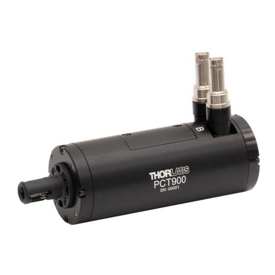
- Page 1 PCT900 Transverse KD*P Pockels Cell, 700 – 1100 nm User Guide...
-
Page 2: Table Of Contents
Chapter 2 Safety ........................... 6 Chapter 3 Installation ........................7 Chapter 4 Operation ........................9 Chapter 5 Maintenance and Cleaning ..................11 Chapter 6 Troubleshooting and Repair ..................11 Chapter 7 Disposal ........................12 Chapter 8 Thorlabs Worldwide Contacts ..................13... -
Page 3: Chapter 1 Introduction
The PCT900 is intended to be used as an optical shutter for frequencies from DC to 250 kHz. It is designed for use as an amplitude modulator and includes a Glan-Laser calcite polarizer as an analyzer to facilitate that. Input light should be linearly polarized and have its plane of polarization oriented parallel to one set of the engraved lines on the front of the part (the side closer to the electrical connectors, see mechanical drawings in Chapter 5). - Page 4 Transverse KD*P Pockels Cell Chapter 1: Introduction applied perpendicular to the optical axis (that is, at right angles to the incoming light beam). The PCT900 is a transverse Pockels cell, which allows for lower voltages to be used. ���� × ����...
-
Page 5: Specifications
Measured at 780 nm for a Ø1 mm beam. Note that the beam diameter is defined by points where the power is 1% of the peak power. This will be 50% larger than the 1/e diameter (Ø0.66 mm) for a Gaussian beam. 1.4.2 Graphs PCT900 Half-Wave Voltage 1000 1100 Wavelength (nm) Figure 1 Half-Wave Voltage vs Wavelength Rev. - Page 6 Transverse KD*P Pockels Cell Chapter 1: Introduction PCT900 Extinction Ratio Beam Diameter (mm) Figure 2 Extinction Ratio vs Beam Diameter Note for Figure 2, the beam diameter is measured between points that are 1% of the peak power, which is 50% larger than the 1/e point for a Gaussian beam.
-
Page 7: Mechanical Drawings
Transverse KD*P Pockels Cell Chapter 1: Introduction 1.4.3 Mechanical Drawings Figure 4 Mechanical Drawing Rev. A, April 19, 2024 Page 5... -
Page 8: Chapter 2 Safety
High Voltage – Use Appropriate Cables Operation of the PCT900 may require voltages and current that may be harmful or even lethal. If using with PCD1K, use supplied SHV cables. Other vendors using lower voltages may interface with BNCs or other connectors. -
Page 9: Chapter 3 Installation
IR laser and a power meter. Beam should be collimated and with minimal divergence, and 1/e beam diameter <1.5 mm. IMPORTANT: the physical aperture of the PCT900 is 3.4 mm in diameter, which is larger than the clear aperture of the device. As noted above, do not overfill the aperture, or use the cell with a 1/e beam diameter of more than 1.5 mm, or damage can occur. - Page 10 Transverse KD*P Pockels Cell Chapter 3: Installation 4. Translate cell (or adjust mirrors) so light is incident on center of input aperture (side closer to electrical connectors) as shown below: Figure 6 Input Aperture 5. Rotate cell (or input polarization) so plane of polarization of input light is parallel to one of the lines on the input side (side closer to electrical connectors) of cell.
-
Page 11: Chapter 4 Operation
Operation Warning: Risk of Electrical Shock Operation of the PCT900 may require voltages and currents that may be harmful or even lethal. Use caution and exercise preventative safety measures to prevent contact between these high voltages and any personnel. The PCT900 has no user serviceable parts. Service should only be performed by trained service personnel. - Page 12 1. Once the cell has been aligned (see Section 3.2 for alignment procedure), connect SHV cables as shown above. PCT900 is designed to be used with its companion driver, which has Thorlabs part number PCD1K. Refer to the manual of the PCD1K driver for operation of that unit.
-
Page 13: Chapter 5 Maintenance And Cleaning
Maintenance and Cleaning The PCT900 should not be disassembled under any circumstances. It is a “wet,” cell that is filled with fluid to counteract the sensitivity to humidity of the KD*P crystal. The only approved cleaning method is the use of dry nitrogen to blow off external dust. -
Page 14: Chapter 7 Disposal
Contact Thorlabs for more information. Waste treatment is your own responsibility. “End of life” units must be returned to Thorlabs or handed to a company specializing in waste recovery. Do not dispose of the unit in a litter bin or at a public waste disposal site. It is the user’s responsibility to delete all private data stored on the device prior to disposal. -
Page 15: Chapter 8 Thorlabs Worldwide Contacts
Transverse KD*P Pockels Cell Chapter 8: Thorlabs Worldwide Contacts Chapter 8 Thorlabs Worldwide Contacts For technical support or sales inquiries, please visit us at www.thorlabs.com/contact for our most up-to-date contact information. Corporate Headquarters Product Manufacturer Thorlabs, Inc. Thorlabs, Inc. 43 Sparta Ave... - Page 16 www.thorlabs.com...
Need help?
Do you have a question about the PCT900 and is the answer not in the manual?
Questions and answers