Table of Contents
Advertisement
Quick Links
Advertisement
Table of Contents

Related Manuals for dynasonics FC-215


Summary of Contents for dynasonics FC-215
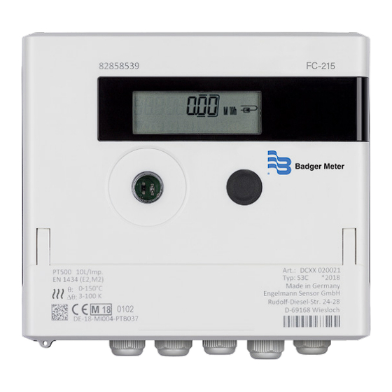
- Page 1 Heat Meter Calculator FC-215 User Manual HYB-UM-04283-EN-01 (January 2024)
-
Page 2: Table Of Contents
Heat Meter Calculator, FC-215 CONTENTS Application and Function Contents of the Package General Information Installation Wall Mounting the Calculator Connecting the Components Mounting the Temperature Sensors Mounting Mounting the Flow Meter Setup of Pulse Value Operation Interfaces and Options Mounting the Power Pack Display Level 2 / Technician’s Loop... -
Page 3: Application And Function
Application and Function DE‐18‐MI004‐PTB037 (MID heat) DE‐18‐M‐PTB‐0049 (national German cooling) CH‐T2‐18769‐00 (national Swiss cooling) OE19 C360 (national Austrian cooling) AV-2484C (Measurement Canada) APPLICATION AND FUNCTION The calculator SensoStar C is designed for the measurement of the consumed energy in a closed heating, cooling or heating/ cooling system Contents of the Package •... -
Page 4: Installation
Installation • Type and concentration of glycol in the medium of those calculator types designed to be used with glycol can be set on location at any time using the Device Monitor software. Pictograms Installation Point of Calculator (in the information loops) On the right in the calculator display in all information loops, you will find one of the following two pictograms The pictogram indicates in which pipe the calculator is to be mounted Installation in outlet flow... -
Page 5: Connecting The Components
Installation Figure 2: Direct screw mounting 131 mm Connecting the Components OTE: First mount the temperature sensors and then connect the flow meter to the calculator This way unnecessary error messages can be avoided At delivery, the display shows H 05 until temperature sensors have been attached This message disappears as soon as temperature sensors have been connected and the first temperature measurement is carried out (every 15 minutes without flow) The calculator connections have been designed to meet the valid standard EN1434-2 All terminal strips have been labelled... -
Page 6: Mounting The Flow Meter
Installation Figure 3: Clamp wires Mounting the Flow Meter The pulse output of the flow meter to be connected to the calculator must be identical to the calculator input pulse value Check the technical data of the flow meter and compare it to the specifications on the calculator •... -
Page 7: Setup Of Pulse Value
Operation Calculators with TX Version OTE: The pulse value will be set permanently after the first input pulses and cannot be changed afterwards Pay attention that the flow meter does not register a flow before the correct pulse value has been chosen (factory setting 1 l/pulse) Figure 6: TX Version calculator display Setup of Pulse Value If the pulse value has not yet been set, follow these steps:... - Page 8 Operation The optical infrared interface will be activated by automatically sending a header (according to EN 13757‐3) Baud rate: 2400 baud Then you can communicate with the calculator for 4 seconds After every valid communication the calculator is open for another 4 seconds Afterwards the display is deactivated The number of read‐outs per day via the optical interface is limited During daily read‐out at least 4 communications are possible If read‐outs are carried out more rarely, the possible number of communications will increase...
-
Page 9: Mounting The Power Pack
Operation Mounting the Power Pack If an external power supply is needed, only the power pack designed for our calculator may be used To connect it to the calculator, open the calculator Remove the battery from the calculator and plug it into the battery connector in the power pack Protect the power pack against unauthorized opening by using one of the numbered adhesive seals enclosed The added bar code label can be used for the purpose of documentation (the battery is a backup in case of a power outage) Remove the left blind grommet in the calculator housing and feed the power pack cable (A) through the cable feedthrough... - Page 10 Operation Level 1 / Main Loop 1) Total heat energy since 2) Segment test on / off 3) Last reading date 4) Total flow volume in m³ start of operation (standard (all segments triggered alternating with heat energy display); alternating display: simultaneously) (cooling energy), volume, cooling energy (for heat/...
-
Page 11: Level 2 / Technician's Loop
Operation Level 2 / Technician’s Loop 1) Current power in kW 2) Current flow in m³/h 3) Inlet flow temperature in °C 4) Outlet flow temperature (When negative flow, value is in °C displayed negative ) 5) Temperature difference 6) Before start of operation: 7) M-bus address 8) Serial number in K... -
Page 12: Level 4 / Maximum Values Loop
Operation Level 4 / Maximum Values Loop 1) Maximum power 2) Maximum flow alternating 3) Maximum inlet flow 4) Maximum outlet flow alternating with date and with date and time temperature alternating with temperature alternating with time date and time date and time 5) Maximum temperature difference alternating with... -
Page 13: Detection Of Flow
Operation By pressing the pushbutton briefly you can switch to the next option By pressing the pushbutton longer the currently displayed option will be set If no option is chosen there will be no change and as soon as the LCD goes out the edit mode will end automatically The following characteristic of those meter types designed to be used with glycol can be set on location at any time using the Device Monitor software:... -
Page 14: Message Descriptions
Operation Example: Temperature sensor 1 cable break Message Alternating hexadecimal message Display location displayed (LCD) Alternating binary message displayed (LCD) When a message appears in the standard display (total heat energy), with the exception of the messages: • Low battery (H 80) •... - Page 15 Heat Meter Calculator, FC-215 THIS PAGE INTENTIONALLY BLANK Page 15 HYB-UM-04287-EN-01 January 2024...
- Page 16 Control. Manage. Optimize. Dynasonics is a registered trademark of Badger Meter, Inc Other trademarks appearing in this document are the property of their respective entities Due to continuous research, product improvements and enhancements, Badger Meter reserves the right to change product or system specifications without notice, except to the extent an outstanding contractual obligation exists ©...
Need help?
Do you have a question about the FC-215 and is the answer not in the manual?
Questions and answers