
Related Manuals for dynasonics TFXL Series


Summary of Contents for dynasonics TFXL Series
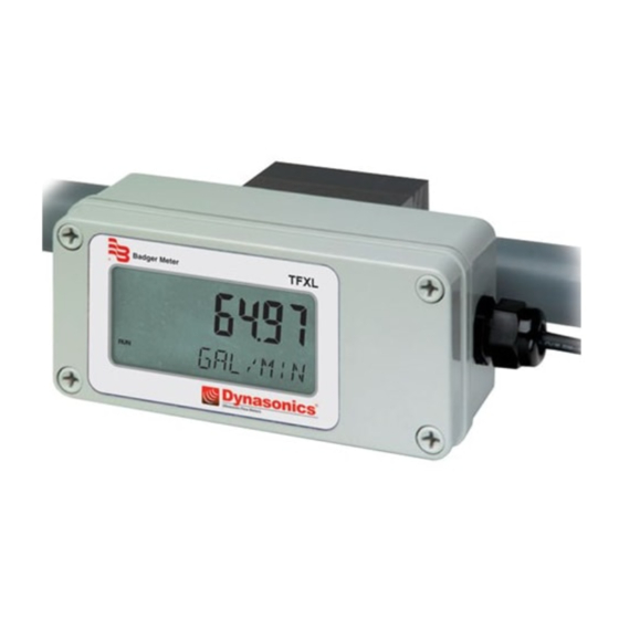
- Page 1 Series TFXL Transit Time Ultrasonic Flow Meter Remote Mount System Operations & Maintenance Manual REV 01/11...
-
Page 3: Table Of Contents
TABLE OF CONTENTS Pages Quick-Start Operating Instructions 1.3 - 1.4 Introduction Part 1 - Introduction General Applications Product Matrix Specifications Terminology Transmitter Installation Part 1 - Transmitter Transmitter Limits and Installation Installation Transducer Connections 1.10 Transmitter Power Connections 1.11 - 1.12 Input/Output Connections and Options Part 1 - Input/Output... - Page 4 TABLE OF CONTENTS Pages Software Utility Operation Part 3 - Programming Programming Entries General Programming Information 3.1 - 3.2 BASIC MENU FLOW MENU 3.4 - 3.6 ADVANCED MENU 3.7 - 3.8 OUTPUT MENU 3.9 - 3.10 DISPLAY MENU 3.11 Flow Meter Calibration 3.12 - 3.14 Appendix Appendix...
-
Page 5: Quick-Start Operating Instructions
QUICK-START OPERATING INSTRUCTIONS This manual contains detailed operating instructions for all aspects of the TFXL instrument. The following condensed instructions are provided to assist the operator in getting the instrument started up and running as quickly as possible. This pertains to basic operation only. If specific instrument features are to be used or if the installer is unfamiliar with this type of instrument, refer to the appropriate section in the manual for complete details. - Page 6 QUICK-START OPERATING INSTRUCTIONS Table 1.1 Transducer mounting method Pipe liner thickness Pipe O.D. (outside diameter) Pipe liner material Pipe wall thickness Fluid type Pipe material Fluid sound speed¹ Pipe sound speed¹ Fluid viscosity¹ Pipe relative roughness¹ Fluid specific gravity¹ ¹ Nominal values for these parameters are included within the TFXL operating system.
-
Page 7: General
PART 1 - INTRODUCTION The TFXL ultrasonic flow meter is designed to measure the fluid General velocity of liquid within a closed conduit. The transducers are a non- contacting, clamp-on or clamp-around type, which will provide benefits of non-fouling operation and ease of installation. TFXL transit time flow meters utilize transducers... -
Page 8: Product Matrix
The serial number and complete model number of each TFXL are Product located on the side of the instrument enclosure. Should technical Identification assistance be required, please provide the Dynasonics Customer Service Department with this information. Product Matrix Transmitter Large Pipe Transducer - Pipes larger than 2" (50 mm) -
Page 9: Specifications
PART 1 - SPECIFICATIONS DESCRIPTION SPECIFICATION Liquid Types Most clean liquids or liquids containing minimal amounts of suspended solids. Power Requirements 11-30 VDC @ 0.25A Velocity 0.1 to 40 FPS (0.03 to 12 MPS) Inputs / Outputs 4-20mA Output (standard output) Totalizer Pulse Resolution 12-bit for all outputs... -
Page 10: Terminology
PART 1 - TERMINOLOGY PC INTERFACE CABLE Rev. 01/11 -1.8- TFXL-X... -
Page 11: Transmitter Installation
In general, it is not recommended to add additional cable to the cable supplied with the DTTN, DTTH, DTTS or DTTC transducers. If additional cable is required, contact the Dynasonics factory to arrange an exchange for a transducer with the appropriate length of cable. -
Page 12: Transmitter Installation
PART 1 - TRANSMITTER INSTALLATION To access terminal strips for electronic connectors, loosen the four Transducer screws in the display lid and remove the cover. The terminals where Connections the transducers connect are located underneath the display. To connect transducers, remove the four screws that secure the display and carefully move it out of the way. -
Page 13: Transmitter Power Connections 1.11
In general, it is not recommended to add additional cable to the cable supplied with the DTTN, DTTH, DTTS or DTTC transducers. If additional cable is required, contact the Dynasonics factory to arrange an exchange for a transducer with the appropriate length of cable. - Page 14 PART 1 - TRANSMITTER INSTALLATION or disconnected, connect the positive supply wire and ground to the appropriate field wiring terminals in the flow meter. See Figure 1.5. A wiring diagram decal is located on the inner cover of the flow meter enclosure.
-
Page 15: Input/Output
The output transmits a continuous current output that is proportional to liquid flow rate. The output was scaled at the Dynasonics factory and the scaling information is recorded on the label located on the side of the TFXL enclosure. -
Page 16: 4-20 Ma Output
PART 1 - INPUT/OUTPUT CONFIGURATION Figure 1.6 4-20 mA Block Diagram Connect the wires to the appropriate Field Wiring Terminals within the TFXL enclosure. See Figure 1.7. 4-20 mA Ground 4-20 mA Output Figure 1.7 4-20 mA Connections Rev. 01/11 -1.14- TFXL-X... - Page 17 PART 1 - INPUT/OUTPUT CONFIGURATION CONNECTING THE PULSE OUTPUT The TFXL is equipped with a circuit that outputs a pulse waveform that varies proportionally with flow rate. The quantity of pulses per unit volume of liquid is described by the K-factor that is recorded on the side of the flow meter enclosure.
- Page 18 PART 1 - INPUT/OUTPUT CONFIGURATION Figure 1.8 Rate Pulse Output Switch Positions RATE PULSE OUTPUT CONNECTIONS Connection of rate pulse output is simply a matter of connecting the two field wiring terminals to the pulse input on the receiving instrument and verifying that the K-factor is programmed into the receiving instrument.
- Page 19 PART 1 - STARTUP AND CONFIGURATION APPLYING POWER TO THE TFXL Before The TFXL flow meter requires a full pipe of liquid before a Starting the successful startup can be completed. Do not attempt to make Instrument adjustments or change configurations until a full pipe is verified. 1.
- Page 20 PART 1 - STARTUP AND CONFIGURATION TFXL1 and TFXL3 Responses — The TFXL1 and TFXL3 are not equipped with a display, so troubleshooting requires the use of a computer and a PC interface cable. See Part 3 of this manual. Rev.
-
Page 21: Transducer Installation
PART 2 - TRANSDUCER INSTALLATION General The transducers that are utilized by the Series TFXL contain piezoelectric crystals for transmitting and receiving ultrasound signals through walls of liquid piping systems. DTTN and DTTH transducers are relatively simple and straight-forward to install, but spacing and alignment of the transducers is critical to the system's accuracy and performance. -
Page 22: Transducer Installation
PART 2 - TRANSDUCER INSTALLATION 1. Mounting Location The first step in the installation process is the selection of an optimum location for the flow measurement to be made. For this to be done effectively, a basic knowledge of the piping system and its plumbing is required. - Page 23 PART 2 - TRANSDUCER INSTALLATION Table 2.1 Straight Pipe Requirements Rev. 01/11 - 2.3 - TFXL-X...
-
Page 24: Transducer Spacing 2.4
PART 2 - TRANSDUCER INSTALLATION 2. Transducer Spacing TFXL transit time flow meters are sold with four different transducer types: DTTN, DTTH, DTTS and DTTC. Meters that utilize DTTN and DTTH transducers consist of two separate sensors that function as both ultrasonic transmitters and receivers. DTTS and DTTC transducers integrate both the transmitter and receiver into one assembly that fixes the separation of the piezoelectric elements. - Page 25 PART 2 - TRANSDUCER INSTALLATION Table 2.2 Transducer Mounting Modes Transducer Pipe Material Pipe Size Liquid Composition Mounting Mode Plastic (all types) Carbon Steel 2-4 in (50-100 mm) Stainless Steel W-Mount Copper Ductile Iron Not recommended Cast Iron Plastic (all types) Carbon Steel 4-12 in (100-300 mm) Stainless Steel...
- Page 26 PART 2 - TRANSDUCER INSTALLATION Table 2.3 Transducer Mounting Modes — DTTS / DTTC Mounting Mounting Size Frequency Transducer Size Frequency Transducer Mode Mode DTTSnP DTTSnP 2 MHz DTTSnC 1-1/4 2 MHz DTTSnC DTTSnT DTTSnT DTTSnP DTTSnP DTTSnC DTTSnC 2 MHz 1-1/2 2 MHz DTTSnT...
- Page 27 PART 2 - TRANSDUCER INSTALLATION Important! The following list of information will be required before programming the instrument. Note that much of the data relating to material sound Enter All of the speed, viscosity and specific gravity are preprogrammed into the Data on this TFXL flow meter.
-
Page 28: Transducer Mounting
PART 2 - TRANSDUCER INSTALLATION 3. Transducer Mounting After selecting an optimal mounting location (Step 1) and successfully determining the proper transducer spacing (Step 2), the transducers can now be mounted onto the pipe. Before the transducers are mounted onto the pipe surface, two Pipe Preparation areas slightly larger than the flat surface of the transducer heads must be cleaned of all rust, scale and moisture. - Page 29 PART 2 - TRANSDUCER INSTALLATION DTTN V-Mount V-Mount and W-Mount Installation and W-Mount For DTTN transducers, place a single bead of couplant, Transducer approximately ½ inch (12 mm) thick on the flat face of the Installation transducer. See Figure 2.2. Generally, a silicone-based grease is used as an acoustic couplant, but any grease-like substance that is rated not to “flow”...
- Page 30 PART 2 - TRANSDUCER INSTALLATION (Top view of pipe) Figure 2.3 Transducer Position Certain pipe and liquid characteristics may cause Signal Strength to rise to greater than 100. The problem with operating a TFXL with very high Signal Strength is that the signals may saturate the input amplifiers and cause erratic readings.
-
Page 31: Dtth High Temp
DTTN instructions on page 2.9 of this manual. DTTS and DTTC Small Pipe Transducer Installation DTTS and DTTC Small Pipe The small pipe transducers offered by Dynasonics are designed for Transducer specific pipe outside diameters. Do not attempt to mount a DTTS or Installation DTTC transducer onto a pipe that is either too large or too small for the transducer—contact the Dynasonics factory to arrange for a... - Page 32 4. If Signal Strength is less than 7, remount the transducer at another location on the piping system. 5. If Signal Strength is greater than 100, contact Dynasonics to obtain a lower power strategy to load into the TFXL meter.
- Page 33 PART 2 - TRANSDUCER INSTALLATION 3. On the pop-up screen, click Next button twice to get to Page 3 of 3. See Figure 2.8. Figure 2.8 Calibration Page 3 of 3 4. Click Edit. 5. If calibration point is displayed in Calibration Points Editor screen, record the information, highlight and click Remove.
-
Page 34: Dttn Z-Mount 2.14
PART 2 - TRANSDUCER INSTALLATION Figure 2.10 Edit Calibration Points 10. After “Writing Configuration File” is complete, turn power off. Turn on again to activate new settings. DTTN Z-Mount Mounting Transducers in Z-Mount Configuration Transducer Installation on larger pipes requires careful measurements to the Installation linear and radial placement of the DTTN and DTTH transducers. - Page 35 PART 2 - TRANSDUCER INSTALLATION Figure 2.12 Bisecting the pipe circumference the template back around the pipe, placing the beginning of the paper and one corner in the location of the mark. Move to the other side of the pipe and mark the pipe at the ends of the crease.
- Page 36 PART 2 - TRANSDUCER INSTALLATION 6. Place the upstream transducer in position and secure with a stainless steel strap or other. Straps should be placed in the arched groove on the end of the transducer. A screw is provided to help hold the transducer onto the strap. Verify that the transducer is true to the pipe—adjust as necessary.
-
Page 37: Mounting Rail
PART 2 - TRANSDUCER INSTALLATION Mounting Rail D010-2102-010 Mounting Rail Installation Installation The D010-2102-010 transducer mounting track is used for pipes that have outside diameters between 2 and 10 inches (50 -250 mm). If the pipe is outside of that range then select a standard V-Mount or W-Mount mounting method. - Page 38 Windows 7 operating system, a communications port, hard disk. Installation 1. ULTRALINK™ can be found on the Dynasonics website for no charge or a CD can be purchased by contacting Dynasonics sales. 2. Backup/Copy all files from the website link to a folder on the computer hard disk.
- Page 39 PART 3 - PROGRAMMING Click on Initialize. Choose the appropriate COM port and interface type. Proper communications are established when a green OK is indicated in the lower right-hand corner of the PC display. NOTE: Power on unit may need to be cycled in order to establish communication.
- Page 40 TFXL. TFXL flow meters with DTTN/DTTH transducers have been constructed and configured at the Dynasonics factory per the specifications provided with each customer order. If the Standard Configuration does not match the pipe schedule or material, select the proper configuration from the drop down list.
- Page 41 PART 3 - PROGRAMMING Flow Units 2. FLOW Tab — See Figure 3.4 Configuration Figure 3.4 Flow Tab Flow Rate Units are selected from the pull down lists. Select an appropriate rate unit and rate time-base from the two lists. ...
- Page 42 PART 3 - PROGRAMMING Table 3.1 Totalizer Exponent Values Exponent Display Multiplier 1 (No multiplier) 1 (No multiplier) 10 100 1,000 10,000 100,000 1,000,000 The Damping value is increased to increase stability of the flow rate readings.
- Page 43 PART 3 - PROGRAMMING Substitute Flow is used to provide an indication and output that signifies that an error exists with the flow meter or its setup. It is set as a percentage between MIN Flow and MAX Flow. In a unidirectional system, this value is typically set to zero to indicate zero flow while in an error condition.
- Page 44 PART 3 - PROGRAMMING Meter Filter 3. ADVANCED TAB — See Figure 3.5 Configuration The Advanced TAB contains several filter settings for the TFXL flow meter. These filters can be adjusted to match response times and data “smoothing” performance to a particular application. The factory settings are suitable for most installations.
- Page 45 Hysteresis is very small and ineffective. This entry is entered in picoseconds and is differential time. This value is factory set and should not be altered without consulting the Dynasonics technical services department. Flow Filter Sensitivity allows configuration of how fast the Flow Filter Damping will adapt in the positive direction.
- Page 46 The label located on the outside of the TFXL enclosure contains information on how the flow meter outputs were configured at the Dynasonics factory. A value that relates flow rate to 4 mA output, flow rate to 20 mA output and K-factor (pulses/gallon) are included on the label.
- Page 47 PART 3 - PROGRAMMING To adjust the range of the 4-20 mA output, simply enter the flow rate that corresponds to 4 mA output in the box titled Flow@100Hz, then enter the flow rate corresponding to 20 mA at @10kHz. Click the Download button and the new range will be established.
- Page 48 PART 3 - PROGRAMMING Display 5. Display TAB — See Figure 3.7 Configuration The Display TAB permits configuration of the flow meter display. Figure 3.7 Display Tab Display Select Flow to display flow rate only on the display. Select Total to display the flow accumulator only on the display. ...
- Page 49 PART 3 - PROGRAMMING Flow Meter Setting Zero and Calibration Calibration ULTRALINK™ contains a powerful multi-point calibration routine that can be used to calibrate the TFXL flow meter to a primary measuring standard in a particular installation. To initialize the three step calibration routine, press the Calibration button located on the top of the ULTRALINK™...
- Page 50 PART 3 - PROGRAMMING Wait for Stable Reading Figure 3.9 Setting Zero Flow The screen shown in Figure 3.10 on page 3.14 allows multiple actual flow rates to be run past the meter and the values recorded by the TFXL. To calibrate a point, establish a stable, known flow rate (verified by a real-time primary flow instrument), enter the actual flow rate in the Figure 3.10 window and press the Set button.
- Page 51 PART 3 - PROGRAMMING Enter Actual Flow Rate Figure 3.10 Flow Rate Calibration Saving Meter Configuration on a PC The complete configuration of the flow meter can be saved from the Configuration screen. Select Save and name the file. This file may be transferred to other flow meters or may be recalled should the same pipe be surveyed again or multiple meters programmed with the same information.
- Page 53 APPENDIX...
- Page 56 Fluid Properties Original Date: 7/30/1999 Revision: Revision Date: 9/10/2003 File: I:/dynasonics/dyna_code/tables/fluid_ss.xls Fluid Specific Gravity Sound Speed delta-v/degree C Kinematic Viscosity Absolute Viscosity 20 degrees C ft/s m/s/degree C Centistokes Centipoise Acetate, Butyl 1270 4163.9 Acetate, Ethyl 0.901 1085 3559.7 0.489 0.441...
- Page 57 Oil, Castor 0.97 1477 4845.8 0.670 0.649 Oil, Diesel 0.80 1250 4101 Oil (Lubricating X200) 1530 5019.9 Oil (Olive) 0.91 1431 4694.9 2.75 100.000 91.200 Oil (Peanut) 0.94 1458 4783.5 Paraffin Oil 1420 4655.7 Pentane 0.626 1020 3346.5 0.363 0.227 Petroleum 0.876 1290...
- Page 58 TFX Error Codes Revised 2-22-2002 Code Number Description Correction Warnings 0001 Serial number not present Hardware serial number has become inoperative – system performance will not be influenced. Signal Strength is below Signal Low signal strength is typically caused by one of the following: 0010 Strength Cutoff entry •...
- Page 59 “STEEL, STAINLESS STEEL, P.V.C. PIPE” STANDARD CLASSES SCH 10 Nominal SCH 5 SCH 20 SCH 30 SCH 40 Outside (Lt Wall) Pipe Size Diameter Inches Wall Wall Wall Wall Wall Wall 1.315 1.185 0.065 1.097 0.109 1.049 1.049 0.133 1.25 1.660 1.53 0.065...
- Page 60 “STEEL, STAINLESS STEEL, P.V.C. PIPE” STANDARD CLASSES Nominal SCH 60 X STG. SCH 80 SCH 100 SCH 120/140 SCH 180 Outside Pipe Size Diameter Inches Wall Wall Wall Wall Wall Wall 1.315 0.957 0.179 0.957 0.179 0.815 0.250 1.25 1.660 1.278 0.191 1.278...
- Page 61 Ductile Iron Pipe (Standard Classes) Class Class Size Size Mortar Mortar Lining Lining (Inches) (Inches) O.D. 3.96 3.96 3.96 3.96 3.96 3.96 O.D. 19.50 19.50 19.50 19.50 19.50 19.50 19.50 Std. 0.123 Std . 0.1875 3” 18” Wall 0.25 0.28 0.31 0.34 0.37...
- Page 62 COPPER TUBING COPPER TUBING Nominal Nominal Copper & Copper & ALUMINUM ALUMINUM Brass Pipe Brass Pipe Diameter Type Diameter Type O. D. 0.625 0.625 0.625 0.840 O. D. 3.625 3.625 3.625 4.000 ½ ” 3½” Wall 0.049 0.040 0.028 0.108 Wall 0.120 0.100...
- Page 63 Cast Iron Pipe (Standard Classes) Class Class Size Size (Inches) (Inches) O.D. 3.80 3.96 3.96 3.96 O.D. 25.80 25.80 26.32 26.32 26.90 26.90 27.76 27.76 3” Wall 0.39 0.42 0.45 0.48 24” Wall 0.76 0.98 1.05 1.16 1.31 1.45 1.75 1.88 I.D.
- Page 64 FPS TO GPM CROSS - REFERENCE (Schedule 40) Nominal I.D. Pipe INCH (Inches) 1.05 2.6989 4.0484 5.3978 6.7473 8.097 9.4462 10.796 12.145 13.490 14.844 16.190 17.540 18.890 20.240 21.590 22.941 24.290 1.25 1.38 4.6620 6.9929 9.3239 11.655 13.99 16.317 18.648 20.979 23.310 25.641 27.970 30.300 32.630 34.960 37.300 39.627 41.958 1.61 6.3454 9.5182 12.691 15.864 19.04 22.209 25.382 28.555 31.730 34.900 38.070 41.250 44.420 47.590 50.760 53.936 57.109...
- Page 65 FPS TO GPM CROSS - REFERENCE (Schedule 40) Nominal I.D. Pipe INCH (Inches) 16.88 697.52 1046.3 1395.0 1743.8 2093.0 2441.3 2790.1 3138.8 3488.0 3836.3 4185.0 4534.0 4883.0 5231.0 5580.0 5928.9 6277.7 18.81 866.14 1299.0 1732.0 2165.3 2598.4 3031.5 3464.6 3897.6 4330.7 4763.8 5196.8 5629.9 6063.0 6496.0 6929.1 7362.2 7795.3 22.63 1253.7 1880.0 2507.0 3134.1 3761.0 4387.8 5014.6 5641.5 6268.3 6895.1 7522.0 8148.8 8775.6 9402.4 10029 10656...
- Page 66 Limited Warranty and Disclaimer Dynasonics, division of Racine Federated Inc. warrants to the end purchaser, for a period of one year from the date of shipment from the factory, that all new transmitters and transducers manufactured by it are free from defects in materials and workmanship.
- Page 67 If you have a question regarding order status, placing an order, reviewing applications for future purchases, or wish to purchase a new flow meter, please contact our new National Sales and Marketing Headquarters: DYNASONICS Division of Racine Federated Inc. 8635 Washington Avenue...
- Page 68 GENERAL TERMS AND CONDITIONS OF SALES 1. PAYMENT – Terms of payment are effective from the actual date of invoice. If, in the Seller’s opinion, the financial condition of the Buyer at any time – or any other circumstances – does not justify the incurrence of production costs of shipment on the terms of payment specified, the Seller may require partial or full payment in advance.
- Page 70 Tel: (800) 535-3569 Fax: (800) 732-8354 Tel: (262) 639-6770 Fax: (262) 639-2267 www.dynasonics.com DYNASONICS is a registered trademark of Racine Federated Inc. Ultralink is a trademark of Racine Federated Inc. ULTEM is a registered trademark of General Electric Co. VESPEL is a registered trademark of E.I. DuPont de Nemours and Company.
Need help?
Do you have a question about the TFXL Series and is the answer not in the manual?
Questions and answers