Table of Contents
Advertisement
Quick Links
Advertisement
Table of Contents

Related Manuals for dynasonics Fusion


Summary of Contents for dynasonics Fusion
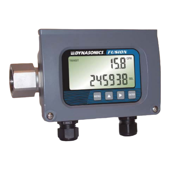
- Page 1 Water Flow Meter Installation and Operating Instructions...
-
Page 3: Table Of Contents
TABLE OF CONTENTS Quick Start Instructions • Operating Theory • Specifications • Mounting Location • Plumbing • Electronic Connections • Power-Up and Operation • Configuration • Configuration—Advanced • Keypad Menu • Troubleshooting • Hazardous Area Installation • Service and Repair •... -
Page 4: Quick Start Instructions
Figure 1—Flow Meter Location 2. PLUMBING FUSION is equipped with an IN directional arrow pointing in the flow direction that will produce positive read- ings with the FLO DIR set to POS. - Page 5 3. ELECTRICAL CONNECTIONS Route 12-30 volt DC power and earth ground through one of the FUSION conduit connec- tions and secure at the 12-30 VDC In, Power Gnd and Earth Gnd terminals. Ensure that electrical codes applicable to the installation area are followed.
-
Page 6: Operating Theory
OPERATING THEORY The FUSION ultrasonic flow meter is designed to measure volu- metric flow of clean, solids-bearing or aerated liquid on full pipes. There are no moving parts to jam or wear and the product can- not be damaged by gas pockets, particulate or high flowing con- ditions. -
Page 7: Specifications
Pressure 300 PSI [2,070 kPa] Temperature -30 to +160 F [-34 to +70 C] Outputs (FUSION cannot output 4-20mA and Rate Pulse simul- taneously. Only one can be selected.) 4-20mA 12-bit; source from DC supply voltage Rate Pulse 0-1,000 Hz; open collector; internal/ external pull-up;... - Page 8 Do not connect or disconnect either power or outputs unless the area is known to be non- hazardous. IMPORTANT NOTE: Do not connect the interface cable between a FUSION flow meter and a personal computer unless the area is known to be non-hazardous.
-
Page 9: Mounting Location
1. MOUNTING LOCATION The first step in the installation process is the selection of an optimum location for the flow measurement to be made. For this to be done effectively, a basic knowledge of the piping system and its plumbing is required. The pipe must be completely filled with liquid while measurements are being made—avoid installations where pipes can become par- tially filled for long periods of time. -
Page 10: Plumbing
2. PLUMBING FUSION is equipped with an IN directional arrow pointing in the flow direction that will produce positive readings with the FLO DIR set to POS. Mount the meter for best viewing of the display re- gardless of the flow direction; the direction can be changed in CONFIGURATION (see page 23). - Page 11 Figure 4. The optimum straight pipe diameter recommendations apply to pipes in both horizontal and vertical orientation. Note: If adequate straight plumbing cannot be provided the FUSION will operate repeatably and reliably, but will not achieve optimum accuracy. Outdoor Installations...
-
Page 12: Electronic Connections
3. ELECTRICAL CONNECTIONS The FUSION flow meter is equipped with three threaded conduit holes located on the bottom of the flow meter enclosure that are suitable for routing of field wiring. A sealed cord grip or sealed threaded conduit connection should be utilized to retain the NEMA 4 integrity of the flow meter enclosure. - Page 13 FUSION enclosure. If the flow meter is only to be utilized as a flow rate indicator or totalizer, no further wiring will be required. Skip to the Flow Me-...
- Page 14 4-20mA CONNECTION The FUSION is equipped with a ground-referenced 4-20 mA output—the output shares a common ground with the power supply. The output transmits a continuous current output that is proportional to liquid flow rate. The output was scaled at the Dynasonics factory and the scaling information is recorded on the label located outside of the FUSION enclosure.
- Page 15 The maximum resistance that the FUSION can accommodate is directly related to the DC power source that is powering the flow meter and the 4-20 mA loop.
- Page 16 K-factor values programmed into them. Unlike standard mechanical flow meters such as turbines, gear or nutating disk meters, the K-factor of the FUSION meter can be changed by modifying the FULL FLOW flow rate value. Please refer to the equations on the following page for the Full Flow / K-factor Calcu- lation.
- Page 17 Rate Pulse Output Connection Figure 10 illustrates the field wiring terminals and switch set- tings utilized for the rate pulse output. Full Flow / K-factor Calculation The Rate Pulse output generates 1,000 Hz (pulses per second) at full flow. To adjust the K-factor of the meter, adjust the full flow entry.
- Page 18 Total Pulse output examples, Example 1: If the Total Unit is set to Gallons and the Total Multi- plier is set to E0 (x1), the FUSION will output one pulse for every gallon of liquid that passes through the meter.
-
Page 19: Power-Up And Operation
4. FUSION POWER-UP FUSION Firmware Version After power is applied to the FUSION flow meter, the display will illuminate and show the software version that is running inside of the flow meter as Ux.xx. Have the firmware version available when contacting factory technical support personnel so that more effective service can be provided. -
Page 20: Configuration
6. CONFIGURATION The FUSION meter has two basic sets of programming proce- dures: list item selection and entering of numeric values. It also has two configuration menus—Basic and Advanced. Important: The FUSION software is structured using two menus—a Basic menu and an Advanced menu. - Page 21 Basic Menu Items The Basic Menu contains standard configuration items that are utilized to setup a FUSION flow meter in common applications. The following items are available for viewing and modification in the Basic Menu:...
- Page 22 MENU key, press key to step through setup. Press ENTER to edit a value. Press ENTER to save a value. M3/H RATE UNIT TOTAL UNIT FLOW DIR 0-9999 Rate Unit FULL FLOW 0-999.9 Rate Unit FLOW C OFF OUTPUT NONE 4-20MA PULSE FAST...
- Page 23 NEG - Reverse Flow Direction. Corrects (shows positive flow) display and outputs if flow is run- ning backwards through the FUSION meter. If flow through the system is in the direction of the IN arrow, the FLO DIR should be set to POS.
- Page 24 1. To change flow cutoff, press the MENU key. 2. Press the key to display FL C OFF on bottom display. Press ► the ENTER key. 3. Press the key to move one digit right and the key to in- ►...
-
Page 25: Configuration-Advanced
RATE TST - Rate Pulse Output Test Allows a fixed frequency to be output from the rate pulse output. By incrementing this value, the rate pulse output will transmit the indicated frequency. The RATE TEST prompt only appears if the output is con- figured for Pulse output. - Page 26 "n" can be from –2 (x0.01) to +3 (x1,000). Table 3.1 should be referenced for valid entries and their influ- ence on the FUSION display. Selection of E-2, E-1 and E0 adjust the decimal point on the display.
- Page 27 Access to resetting of the Totalizer is also protected by this password. If the FUSION password is lost or forgotten, contact the Dyna- sonics factory for a universal password to unlock the meter. 4-20CAL - Calibration of the 4-20 mA Output...
- Page 28 justment. To adjust the 4 mA output, a milliampmeter or reliable reference must be connected to the 4-20 mA output. Procedure: 1. Disconnect the current loop output and connect the milliamp- meter in series between the 4-20mA output and the recording device.
- Page 29 0.001 to 9.999. The following example describes using the DOP SPAN entry. • The FUSION meter is indicating a flow rate that is 4% higher than another flow meter located in the same pipe line. make the FUSION indicate the same flow rate as the other meter, enter a DOP SPAN of 0.960, to lower the readings by...
- Page 30 mode. Typically, this would only be required at very low flow rates. When MANUAL mode is selected, the GAIN POT and FILTER set- tings are manually set. Automatic control is disabled. GAIN POT - Digital Gain Pot 0-64 Using the arrow keys, increase or decrease the numerical value to set the signal gain level.
- Page 31 ERROR will be displayed. Press the Enter key to continue. 1. Block a full pipe of liquid within the FUSION flow meter using ball valves. If the unit indicates EMPTY PIPE, not enough liq- uid was caught and the blocking procedure will need to be completed again.
- Page 32 To make the FUSION indicate the same flow rate as the other meter, enter a TT SPAN of 0.960, to lower the readings by 4%. MODBUS -- Modbus interface configuration Modbus setup mode allows access to the following parameters.
- Page 33 Opcode 04 – Read Input Registers This opcode returns the input registers, such as flow rate or to- talizer. All data is returned as 16 bit values with the MSB first as required by Modbus The following Input Registers are defined: Modbus Register Starting Address Description...
- Page 34 Opcode 05 – Force Single Coil This opcode sets the state of a single coil (digital output). The following Coil Registers are defined: Coil # Description 1..8 Spare Reset Totalizer 10.16 Spare The transition of coil 9 from 0 to 1 will initiate function. This bit is auto reset to 0, so there is no need to set it to 0 after a totalizer reset command.
- Page 35 C Source Code A.1.1 CRC-16 Calculations unsigned short crc_table[256] = { 0x0000, 0xC0C1, 0xC181, 0x0140, 0xC301, 0x03C0, 0x0280, 0xC241, 0xC601, 0x06C0, 0x0780, 0xC741, 0x0500, 0xC5C1, 0xC481, 0x0440, 0xCC01, 0x0CC0, 0x0D80, 0xCD41, 0x0F00, 0xCFC1, 0xCE81, 0x0E40, 0x0A00, 0xCAC1, 0xCB81, 0x0B40, 0xC901, 0x09C0, 0x0880, 0xC841, 0xD801, 0x18C0, 0x1980, 0xD941, 0x1B00, 0xDBC1, 0xDA81, 0x1A40, 0x1E00, 0xDEC1, 0xDF81, 0x1F40, 0xDD01, 0x1DC0, 0x1C80, 0xDC41, 0x1400, 0xD4C1, 0xD581, 0x1540, 0xD701, 0x17C0, 0x1680, 0xD641,...
-
Page 36: Keypad Menu
Advanced Menu Map... - Page 37 Advanced Menu Map...
- Page 38 Basic Menu Map...
-
Page 39: Troubleshooting
Troubleshooting Display does not 1. Check DC voltage at terminal strip illuminate 2. Check display ribbon cable 3. FUSION meters are equipped with automatic reset fuses. Output does not 1. Verify that 4-20mA or Rate PULSE is match displayed properly selected in the OUTPUT selec- flow value tion. -
Page 41: Service And Repair
(800) 535-3569 or (262) 639-6770 to obtain an RGA number for the authority and tracking of your material and its proper inspection and return. All returns of equipment must go to the following address: Dynasonics Attn: RGA#xxxx 8635 Washington Avenue Racine, WI 53406... -
Page 42: Warranty Statement
Dynasonics and found to be defective. Repair or replacement is at Dynasonics dis- cretion. A return goods authorization (RGA) number must be ob- tained from Dynasonics before any product may be returned for warranty repair or replacement. - Page 43 NOTES:...
- Page 44 8635 WASHINGTON AVENUE RACINE, WI 53406 TOLL-FREE IN U.S. and Canada.: TEL: (800) 535-3569 FAX: (800) 732-8354 TEL: (262) 639-6770 FAX: (262) 639-2267 URL: www.dynasonics.com FUSION O&M REV 1/08...
Need help?
Do you have a question about the Fusion and is the answer not in the manual?
Questions and answers