Table of Contents
Advertisement
Quick Links
Advertisement
Table of Contents

Related Manuals for dynasonics TFXL


Summary of Contents for dynasonics TFXL
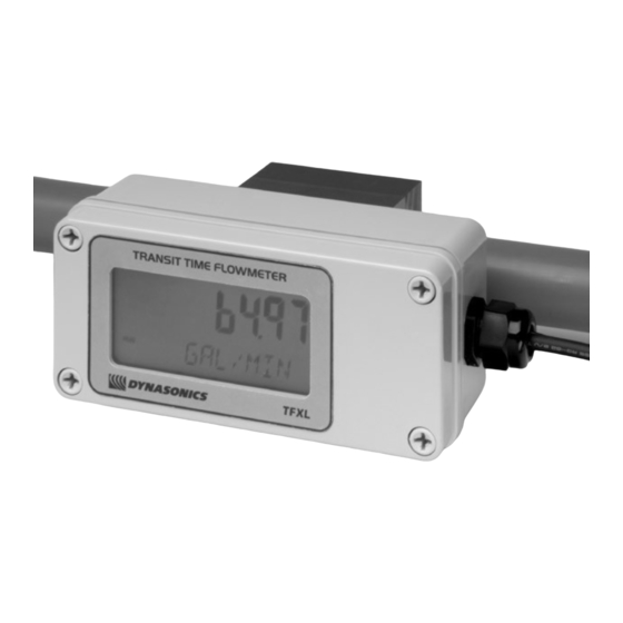
- Page 1 MODEL TFXL ULTRASONIC FLOW METER Installation and Operating Instructions...
-
Page 3: Table Of Contents
TABLE OF CONTENTS • Quick Start Instructions • Introduction • Specifications • Symbol Explanations • Components and Terminology • Flow Meter Mounting Procedure • Electronic Connections • 4-20mA Output Connections • Pulse Output Connections • Applying Power • Software Utility •... -
Page 4: Quick Start Instructions
QUICK-START INSTRUCTIONS This manual contains detailed operating instructions for the TFXL instrument. The following condensed instructions are provided to assist an experienced operator in basic operation of the instrument. If the operator is unfamiliar with this type of instrument, refer to the detailed explanations located on pages 10- A. - Page 5 DO NOT ROTATE the flow meter on the pipe once the screws have been tightened. E. Connect 11-30 Vdc to the power terminals within the TFXL transmitter. Ensure that the power supply is capable of sourcing a minimum of 0.25 Amps. Observe polarity.
-
Page 6: Introduction
The TFXL compensates for gas content in the liquid and will remove gaseous content from flow rate and totalizer readings. Outputs from the flow meter include 4-20 mA analog, turbine frequency output/ pulse output. -
Page 7: Specifications
SPECIFICATIONS/OPERATING CONDITIONS For a complete table of specifications, see Data Sheet DTFXL Description Specification Input Voltage 11-30 VDC @ 0.25A Flow Range Reference 0.8 to 40 FPS [0.25 to 12.4 MPS] Sch 40 ½” Pipe 0.5 to 25 GPM [20 to 850 BPD] Sch 40 ¾”... -
Page 8: Components And Terminology
FLOW METER COMPONENTS AND TERMINOLOGY The pictures on the following two pages reference key components and their respective terminology of the TFXL flow meter. These terms are utilized throughout this manual. - Page 9 SOUND GUIDES CLAMP PC INTERFACE CABLE...
- Page 10 Do not connect or disconnect either power or outputs unless the area is known to be non- hazardous. IMPORTANT NOTE: Do not connect the interface cable between a TFXL and a personal computer unless the area is known to be non-hazardous.
-
Page 11: Flow Meter Mounting Procedure
The optimum straight pipe diameter recommendations apply to pipes in both horizontal and vertical orientation. Note: If adequate straight plumbing cannot be provided the TFXL will operate repeatably, but will most likely not achieve ideal accuracy. Figure 4—Straight Pipe Recommendations... - Page 12 B. MOUNTING ORIENTATION ON THE PIPE If the flow meter is applied to horizontal pipe, choose a mounting position within approximately 45-degrees of 3 o’clock or 9 o’clock on the pipe, assuming 12 o’clock to be to top of the pipe. These positions provide optimum acoustic penetration into the moving liquid.
- Page 13 To assure an acoustically conductive path between the transducer face and the prepared pipe surface, a coupling compound is employed. Enclosed with the TFXL flow meter is a tube of silicone based grease. This grease is adequate for the majority of installations. If an alternate grease is utilized, the grease must be specified not to flow at the temperature of the pipe surface or the ambient conditions.
-
Page 14: Electronic Connections
F. FIELD WIRING—GENERAL The TFXL is equipped with a single conduit hole located in the flow meter enclosure that should be suitable for most installations. A sealed cord grip or conduit connection should be utilized to retain the NEMA 3 integrity of the flow meter enclosure. - Page 15 Do not connect or disconnect either power or outputs unless the area is known to be non-hazardous. Power for the TFXL flow meter is obtained from a direct current DC power source. The power source should be capable of supplying between 11 and 30 Vdc at a minimum of 0.25 Amps or 250 milliamps.
-
Page 16: 4-20Ma Output Connections
The output was scaled at the Dynasonics factory and the scaling information is recorded on the label located on the side if the TFXL enclosure. To ensure that the instrument or data acquisition system that is receiving the 4-20 mA signal responds properly, it must be spanned identically to the TFXL. - Page 17 Loop Resistance 4-20 mA Ground Power Supply Ground Figure 8 4-20 mA Block Diagram Connect the wires to the appropriate Field Wiring Terminals within the TFXL enclosure. See Figure 9. 4-20 mA Ground 4-20 mA Output Figure 9 4-20 mA Connections...
-
Page 18: Pulse Output Connections
I. CONNECTING THE PULSE OUTPUT The TFXL is equipped with a circuit that outputs a pulse waveform that varies proportionally with flow rate. quantity of pulses per unit volume of liquid is described by the K-factor that is recorded on the side of the flow meter enclosure. - Page 19 Field Wiring Terminals to the turbine meter input terminals on the receiving instrument and verifying that the K-factor listed on the side of the TFXL enclosure is programmed into the receiving instrument. This output is not referenced to DC ground and is not polarized, so wiring polarity is not important.
-
Page 20: Applying Power
TTL Pulse Output Connections J. APPLYING POWER TO THE TFXL The TFXL flow meter requires a full pipe of liquid before a successful startup can be completed. Do not attempt to make adjustments or change configurations until a full pipe is verified. - Page 21 ⇒ A negative value would indicated that flow is moving backwards—against the flow direction arrow. A standard TFXL will not output flow signals under this condition. ⇒ The flow meter indicates flow rate. This verifies that signal strength is adequate and that the flow is moving in the direction that the flow arrow signifies.
-
Page 22: Software Utility
ULTRALINK COMPUTER SOFTWARE The UltraLink utility has been designed to provide the TFXL user with a powerful and convenient way to configure, troubleshoot and calibrate TFXL flow meters. Several operating features can be setup or revised from factory set values using the UltraLink utility. - Page 23 TFXL and a personal computer unless the area is known to be non-hazardous. 1. Connect the PC to the TFXL flowmeter by connecting the PC interface cable between a COM port on the PC and the PC Interface connection within the TFXL flow meter—See Page 8 for location of the connector.
- Page 24 3. The opening screen, shown in Figure 12, is called the Data Screen. It contains a large data trend chart that can be adjusted for both the X(time) and Y(flow rate) axis. This screen also contains real-time information regarding flow rate, totalizer accumulations, system signal strength and diagnostic data.
- Page 25 Scientific Notation values and their respective decimal equivalents. • MIN Flow is used by the TFXL to establish filter settings in its operating system. Enter a flow rate that is the minimum flow rate anticipated within the system. For uni-directional systems, this value is typically zero.
- Page 26 Figure 14 Flow Tab TABLE 1—Totalizer Exponent Values Exponent Display Multiplier X 1 (No multiplier) X 1 (No multiplier) X100 X1,000 X10,000 X100,000 X1,000,000...
- Page 27 • MAX Flow is used by the TFXL to establish filter settings in its operating system. Enter a flow rate that is the maximum, positive flow rate anticipated within the system. • The Damping value is increased to intensify stability of the flow rate readings.
- Page 28 Download button to transfer the configuration to the TFXL instrument. 7. ADVANCED TAB—See Figure 15 The Advanced TAB contains several filter settings for the TFXL flow meter. These filters can be adjusted to match response times and data “smoothing” performance to a particular application.
- Page 29 Figure 15 Advanced Tab • Flow Filter Damping establishes a maximum adaptive filter value. Under stable flow conditions (flow that varies less than the Flow Filter Hysteresis entry) this adaptive filter will increase the number of successive flow readings that are averaged together up to this maximum value.
- Page 30 The entries made in the Output TAB establish range factors for the 4-20 mA and frequency outputs on the meter. The 4-20mA is calibrated at the Dynasonics factory and cannot be altered in the field. However, the range of the output can be altered.
- Page 31 Figure 16 Output Tab 1) To determine the frequency out of a turbine meter at maxi- mum flow, convert the maximum flow rate to gallons/second, then multiply by the nominal K-factor (pulses/gallon). 2) Calculate the flow rate that corresponds to 1000Hz. Multiply the maximum flow rate times 1000Hz, then divide by the re- quired frequency at maximum flow.
- Page 32 To adjust the range of the 4-20mA output, simply enter the flow rate that corresponds to 4mA output in the “Flow @0Hz” field. Enter the flow rate that corresponds to 20mA output in the “Flow @ 1KHz” field. 9. Display TAB—See Figure 17 The Display TAB permits configuration of the flow meter display.
- Page 33 Display Dwell Time • Enter a value between 1 and 10 seconds to establish how long the flow meter will display flow rate, then accumulated total, then rate and so on. Figure 17 Display Tab...
- Page 34 Setting Zero and Calibration UltraLink contains a powerful multi-point calibration routine that can be used to calibrate the TFXL flow meter to a primary measuring standard in a particular installation. To initialize the three step calibration routine, press the Calibration button located on the top of the UltraLink Data Screen.
- Page 35 The second screen, Figure 19, establishes a baseline zero flow rate measurement for the instrument. To zero the flow meter, establish zero flow in the pipe (turn off all pumps and close a dead-heading valve). Wait until the delta-time interval shown in Figure 19 is stable (and typically very close to zero).
- Page 36 Flow Rate Calibration The screen shown in Figure 20 allows multiple actual flow rates to be run past the meter and the values recorded by the TFXL. To calibrate a point, establish a stable, known flow rate (verified by a real-time primary flow instrument), enter the actual flow rate in the Figure 20 window and press the Set button.
-
Page 37: Maintenance
Saving Meter Configuration on a PC The complete configuration of the flow meter can be saved from the Configuration screen. Select Save and name the file. This file may be transferred to other flow meters or may be recalled should the same pipe be surveyed again or multiple meters programmed with the same information. -
Page 38: Troubleshooting Guide
• If the voltage is present and neither LED on the main printed circuit board is illuminated, return the flow meter to the Dynasonics factory for evaluation. • Unit reads zero flow when Verify that the Maximum Flow Rate flow is actually running... -
Page 39: Warranty
STATEMENT OF WARRANTY Dynasonics Division, Racine Federated, Inc. (hereinafter “the Company”) warrants its products under normal use and service to be free of defects in material and workmanship for a period of twelve (12) months from date of shipment (the “Warranty Period”). -
Page 40: Service Instructions
(800) 535-3569 or (262) 639-6770 to obtain an RGA number for the authority and tracking of your material and its proper inspection and return. All returns of equipment must go to the following address: Dynasonics Attn: RGA#xxxx 8635 Washington Avenue Racine, WI 53406... -
Page 42: Notes
NOTES... - Page 44 8635 WASHINGTON AVENUE RACINE, WI 53406 TOLL-FREE IN NORTH AMERICA.: TEL: (800) 535-3569 FAX: (800) 732-8354 TEL: (262) 639-6770 FAX: (262) 639-2267 URL: www.dynasonics.com TFXL O&M REV 11/05...
Need help?
Do you have a question about the TFXL and is the answer not in the manual?
Questions and answers