
Related Manuals for Laspaziale S21


Summary of Contents for Laspaziale S21
- Page 1 Subscribe to DeepL Pro to translate larger documents. Visit www.DeepL.com/pro for more information. EN 00 LSI 026 08- 2022...
-
Page 2: Installer Manual
INSTALLER MANUAL... -
Page 3: Weee
WEEE Disposal of equipment by individuals in the territory of the European Union (WEEE), according to the standards 2011/65/EU, 2012/19/EU and 2015/863/EU, related to the reduction of the use of hazardous substances in electrical and electronic equipment, as well as waste disposal. The crossed-out bin symbol on the equipment or its packaging indicates that the product at the end of its useful life should be collected separately from other waste. -
Page 5: Table Of Contents
INDEX ELECTRIC IGNITION OF THE COFFEE MACHINE .......15 WEEE......................II 5.1 COFFEE DOSAGE PROGRAMMING (EK only)......16 5.2 BOILER PRESSURE REGULATION..........17 5.3 PUMP PRESSURE ADJUSTMENT...........19 1. GENERAL DESCRIPTION OF THE MACHINE ........2 5.4 LED BRIGHT INTENSITY ADJUSTMENT (optional)....19 1.1 COFFEE BREWING BUTTON DESCRIPTION........3 5.5 ITC SYSTEM (optional)...............20 ........................ -
Page 6: General Description Of The Machine
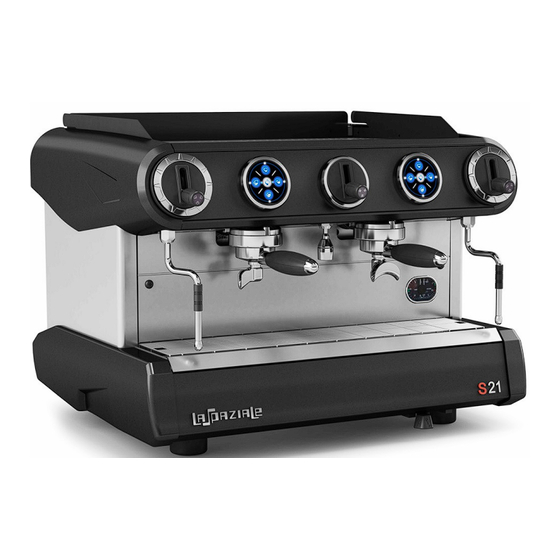
1. GENERAL DESCRIPTION OF MACHINE group. 5. RIGHT steam tap. 19 18 12 17 11 10 LEGEND: 1. Left steam tap. 6. RIGHT steam lance. 11. Hot water lance. 2. Push-button panel 2nd 7. Pressure gauge. 12. Filter holder 1 coffee. group. - Page 7 16. Backlit ring*. 17. Gas inspection window*. 18. Piezo Gas Igniter*. 19. Gas tap knob*. * Optional. EN 00 LSI 026 08- 2022...
-
Page 8: Hand Control
1.1 DESCRIPTION BUTTON PANEL DISPENSING COFFEE LEGEND: EK HAND CONTROL PULSION EP A. Button 1 short coffee. F. Button 2 long coffees. M. Led continuous dispensing button. B. Led Continuous Dispensing Button. G. Led Button 2 long coffees. N. Continuous dispensing button. C. -
Page 10: General Tips For The Installer
2. GENERAL TIPS FOR THE INSTALLER Carefully read the instructions and warnings contained in this manual and in the "USE AND MAINTENANCE MANUAL," a s they provide important information regarding the installation of the appliance. Warning. The device may be used only for the purpose for which it was intended. Any other use is to be considered improper, and therefore unreasonable. - Page 11 Danger! Should it be necessary to replace the power cord of the device, use only the following types: CET ELETRIC H07RN-F 5 x 2.5 mm (400V) for 2/3-group versions, 5 x 4 mm (400V) for 4-group versions - CET ELETRIC SINGLE-PHASE 3 x 2.5 mm (220V) 2-group versions, 3 x 4 mm (220V) for 3/4-group versions.
- Page 12 Warning. Installation must be done by qualified personnel and according to the manufacturer's instructions. Incorrect installation may cause damage to people, animals or property, for which the manufacturer cannot be held responsible. Warning. Place the device on a supporting surface, the stability of which must be checked. Warning.
-
Page 13: Removal Of Packaging
3. PACKAGING REMOVAL After unpacking, check the integrity of the appliance; if in doubt, do not use it and contact the manufacturer. Packaging items should not be left within the reach of children as they are potential sources of danger. Warning. -
Page 14: Installation
4. INSTALLATION Place the machine on a supporting surface, lifting it only from below. Before connecting the machine to the power supply, make sure the data on the nameplates match the specifications of where it is installed. 4.1 INSTALLATION WIRING DIAGRAM During electrical connection, refer to all warnings and suggestions in this manual. - Page 15 Danger! The blue wire (D) is connected to the neutral of the 'electrical system. Note. 230-volt connections are possible only if the nameplate shows a power rating of less than 6300 W. EN 00 LSI 026 08- 2022...
-
Page 16: Hydraulic Installation Diagram
4.2 HYDRAULIC INSTALLATION DIAGRAM Warning. The machine is supplied without water in the boiler to prevent 'any exposure to a temperature below 0° C, may cause irreparable damage. Legend: 1 Water tap (previously placed by the customer). 2 Motor pump (supplied with the machine-if not integrated). 3 Water treatment system (optional). - Page 17 Danger! THE INSTALLATION OF A WATER TREATMENT SYSTEM IS RECOMMENDED TO PROLONG THE LIFE OF THE MACHINE. Before installing the machine, check the water hardness and, if necessary, install the 'water treatment system according to the manufacturer's instructions and current regulations. Danger! In the absence of a water treatment system in the plumbing system, a filter should be attached to the inlet hose of the motor pump to prevent the entry of impurities, which could damage the motor pump or the machine.
-
Page 18: Exhaust System
4.3 EXHAUST SYSTEM Connect the plug-in drain hose to the hose holder on the machine's sump and place the other end directly into the U-shaped drain hose of the prepared drainage system. Ensure that the hose is not obstructed or crushed in its length and that it is angled enough to drain smoothly. -
Page 19: Gas System (Optional)
4.4 GAS PLANT (optional) LEGEND: 1. Gas tap (previously installed by the customer). 2. Gas supply pipe. Note. The appliance is set up by the manufacturer to operate with LPG gas (G30). When connecting the appliance to the 'system, use only hoses suitable for the type of gas used and in accordance with applicable laws. -
Page 20: Gas Table
4.5 GAS TABLE. Note. Nozzle bore (Ø) is expressed in hundredths of a mm. These values refer to the warm-up phase of the machine, that is, when the gas pressure switch is fully open (with flame at maximum). Adaptation to a different type of gas is done by replacing the nozzle as indicated in the following instructions and complying with the conditions given in the gas table. -
Page 21: Electric Ignition Of The Coffee Machine
& MAINTENANCE MANUAL included with the appliance. Note. For possible ordering of spare parts, see the spare parts catalog available in the 'restricted area of the website www.laspaziale.com. Wait for the unit to reach the thermal steady state pressure, indicated by the pressure gauge (7, p. -
Page 22: Coffee Dosage Programming (Ek Only)
5.1 COFFEE DOSAGE PROGRAMMING (only EK) Within 30 seconds place a Hold down continuous Press the button a 1 short coffee, filter holder, containing a dose of dispensing button on the first button once the required dose of coffee is ground coffee, to the group and place from the right, for about 5 seconds, reached, press the same button... -
Page 23: Boiler Pressure Regulation
Danger! By setting doses on the first right hand button panel, the other groups will automatically acquire the same dosage; if you want to set a different dosage per group, repeat the same setting procedure on the button panel corresponding to the group to be programmed differently. - Page 24 Note. The pressure switch is located on the right side of the machine; to access it, remove the bowl and grate. Remove the yellow protective cap to access the adjustment screw. Danger! Remove power from the device if you need to act on the pressure switch. Note.
-
Page 25: Pump Pressure Adjustment
5.3 PRESSURE REGULATION PUMP The suitable working pressure is between 8 and 10 bar. That pressure can be visualized by turning on a regulator assembly on the machine's pressure gauge (7, p. 2). To adjust the pressure, act on the adjustment screw (1) on the motor pump, after loosening the lock nut (if any). -
Page 26: Itc System (Optional)
5.5 ITC SYSTEM (optional) This system allows a different coffee ero- gation temperature to be set for each group. The temperature of each group is independent of the temperature set in the boiler. To change the temperature of a group, use the respective flow regulator, which is accessible through the opening on the top of the cup rest top (3). -
Page 27: Alarm Management
6 ALARM MANAGEMENT EK MODEL MODEL EP BUTTON PANEL LEDS FLASH THE LED RELATED TO THE COFFEE DOSE BEING BREWED FLASHES AFTER 5-6 SECONDS: ALTERNATELY: This alarm is displayed when, during dispensing, there is The automatic load of 'water in the boiler remained on beyond the a malfunction of the volumetric system related to the group in 4 minutes (6 minutes for the 3-group), total blockage of the machine. -
Page 28: Hydraulic Scheme
7 HYDRAULIC SCHEME LEGEND: R = WATER MAINS TAP VDR = DOUBLE CHECK VALVE A = WATER TREATMENT SYSTEM (OPT.) F = WATER FILTER (OPTIONAL) MP = MOTOPUMP VU = CHECK VALVE VE = EXPANSION VALVE G1 = WATER MAINS/PUMP PRESSURE GAUGE EVA = SELF-LEVEL SOLENOID VALVE G2 = BOILER PRESSURE GAUGE F1 = VOLUMETRIC METER 1ST GR F2 =... -
Page 29: Wiring Diagram
7.1 WIRING DIAGRAM S21 SPACE S21 2 GR 220-240 VOLTS S21 2/3 GR 400 VOLT ELECTRONIC CONTROL UNIT EN 00 LSI 026 08- 2022... -
Page 30: Wiring Diagram And Legend
7.2 WIRING DIAGRAM AND LEGEND LEGEND: CUP WARMER LED LIGHTING HEATING BOILER ELECTRICAL ELEMENT RESISTANCE SAFETY THERMOSTAT PS = PRESSURE SWITCH MB = ELECTRONIC CONTROL UNIT MS = MAIN SWITCH F = PHASE N = NEUTRAL G = MASS MP = MOTOPUMP EV1 = SOLENOID VALVE 1ST COFFEE GROUP SOLENOID... -
Page 31: La Space Thermal System
LP = LED WORK SURFACE LIGHTING EN 00 LSI 026 08- 2022... - Page 32 7.3 THERMAL SYSTEM THE SPACE All LA SPAZIALE espresso machines, are built with a heat exchange system between the boiler and the coffee group. A special patent, unique in the world, for the thermoregulation o f the coffee brewing group based on the circulation of steam instead of water.
- Page 33 Space S.p.A. E. Duse Street, 8 40033 Casalecchio di Reno Bologna - (Italy) +39 051 611.10.11 +39 051 611.10.11 info@laspaziale.com Design by LA SPAZIALE S.p.A. EN 00 LSI 026 08- 2022...
Need help?
Do you have a question about the S21 and is the answer not in the manual?
Questions and answers